When you click on links to various merchants on this site and make a purchase, this can result in this site earning a commission. Affiliate programs and affiliations include, but are not limited to, the eBay Partner Network.
I painted the inside of my rotors while they spun o the lathe. I did however use enamel spray paint that I layed thick layers on.
Brushing would be a nightmare for an Item that will need replacing sooner than the rest of the car.
In my opinion you would have been better off by buying replacement rotors as New rotors have yet to start pitting from rust.
This way you can also get a nice/sleek coating applied to them which in your end will be easier to do.
Yes I was brainstorming how I could make a shrouded hood around the rotors and spray heavily enough to get complete coverage then turning them while dripping wet and fling off the excess to get a uniform coat inside the vanes. That would be easier than trying to brush inside them.
My hats and edges aren't that bad, still had the black matte coating, it just has rust inside the vanes and on the backs or on the inside.
I wish there were supercars' or whatever has oem carbon ceramic rotors that would coincidently fit the g37 that I could buy used on ebay but the specs would never match. Haha.
Last edited by Justin Bailey; 10-07-2019 at 03:31 PM.
I'm not entirely sure how carbon ceramic rotors are mounted, but I assume they're two-piece as most performance rotors are. You could find some carbon replacement rotor rings (355mm x 32mm or close - they must sell those somewhere, right?), machine a hat for them to fit, and possible offset the caliper if necessary.
edit: you had me go down a rabbit hole of stuff I didn't think I needed to know today.
I saw them a while back from wilwood, but for that money it would be cheaper to buy the Z1 2 piece ones and an few inconel 718 plates and have them custom machined to match the rotors for those hats.
Found a few adequately sized planter saucers at a box store to speed up the process.
It only takes a little over a half gallon for the rears and about 1 gallon for the fronts to submerge the rotor parts instead of 2-1/2 just for one in the rectangle pan.
Got back to the sway bar brackets which were in stripper in a container for like a month. A little deburring and sanding smoothened the sharp egdes.
Three light coats of rust seal, (2 galvanized ans one silver). No runs this time.
At first I did the alternator and crank pulleys with rust seal with a brush, but sanded it smooth and recoated with pontiac blue metallic engine enamel. Then scuffed and did the other pulleys. This is the hirsch stuff, I got the eastwood but burned it up because it was a paler color and not as nice.
A mix of galv and black rust seal make a grey for these anchor blocks. Not sure but may coat the threads lightly with plain galv. They take a lock nut though.
Last edited by Justin Bailey; 10-14-2019 at 12:09 PM.
Polished the thermostat and decided to try the alodine and the cerakote first on this.
Just plain polished and cleaned with dawn soap first. I reduced the tabs that are on each side as hose stops just to polish it easier. Also rounded off the nissan square casting part and a a seam line on the back of the angle, just to make it easy to polish.
The cleaner etch I mixed 1:5 product/water and the conversion coating 40/60 with water. Used a soft toothbrush with the cleaner and rinsed a few times until I saw there was a no beading showing the oils were gone. Then the exposure with the conversion is 15-30 sec. and rinse.
The cleaner kind of produced a satin effect which looses some of the highly polished look but is ok to me because it helps ensure maximum anti corosion protection. The cerakote goes on in one coat really easy. I am satisfied with how this system worked, but the cerakote directions only require a simple dawn dish soap cleaning first if you want the full polished effect to shine through.
The conversion coating also helps ensure the best possible adhesion to the aluminum, the risk of having any kind of cloudy finish with simply clear coating the plain polished surface is kind of a non issue since it clouds and satin colors the metal before hand. I think it makes it look like a manufactured piece in a way like you would find already made and treated off the shelf, but the mc5100 cerakote is formulated specially for aluminum as well.
It will help hide dirt also, if it was a show car or garage queen it would be nicer to go with just the clear over the plain polished metal.
Btw, this is an air cure coating, no need to bake, and it handles up to 400 deg. F.
It's funny how the oem thermostat is like a $25 part but a 'racing' temp one that probably only has a different $10 spring is over $100.
Last edited by Justin Bailey; 10-15-2019 at 02:13 PM.
Did the same on this large peice, it has 2 coats. It has very good self leveling so at first the second coat, about 10 min apart, looked orange peely, but went away. The coating has an oily feel when wet, it takes up to an hour to be dry to touch, but says full cure is after 24 hrs.
After the satin treatment effect, it is easy to see flaws and places where I could have polished more, but it 's mostly pinpoints and extreme corners, and even then it's only in a few places. Seeing now, I could have completely gotten rid of that marking over where the starter mounts, but it's ok.
Overall, I'm happy with it. I allowed it to coat over the mating surfaces and sprayed up under the other side, so it won't corrode in between there after mounted and it happens to wick in moisture.
Got a lot of bolts back from a machinist who used a real metal lathe to turn down larger bolts to use for their large head diameter to match oem head diameters, these were 5/8-18 thread, now M12 1.25. Inconel 718. They are a bit longer but they tighten without bottoming out. OE flange diameters are 25.90 mm and these are 26.70 just a mm or so wider.
I had some 304 stainless steel scrap about 3.5mm thickness identical to the original suspension radius rod link to sub frame attachment captive washer bolt. Made some card stencil to trace out the shape. A hacksaw and some rough grinding then stacked them onto the original and held with a large nut in a drill press vise and used a straight burr to squarely get up to the lines, then a process of clamping the pair in alternating orientaions and hand filing produced a really semetrical set. Then flat files really got them flat and took out vise marks.
The washers fit tight until they get down the the head of the bolt then spin freely. The originals' threads were rolled after the washers were added making them captive. Just more fancy 12 point stainless do'dads.
Last edited by Justin Bailey; 11-03-2019 at 12:24 PM.
If I had done it over again I would have just bought a set of 10 5/8 bolts like these, drilled out the heads and threaded them and cut off the shanks to make the sub frame nuts from the inconel instead of titanium, but the ti ones are stout enough, that money was already spent. That was before I found the right cobalt taps and dies that would cut into this material well enough. It would have been cheaper and produced stronger nuts, and the ti ones' thread fit is ok about the same as original but could have been made tighter, but I didn't really specify it to the manufacturers at the time. They are certainly good enough, but they are unequalled by the thread tolerance this machinist has produced on these latest pieces.
I actually used a nut and some 1 micron diamond paste to work over the end 1/2" or so of the crank bolt so I could turn it all the way in with my fingers. If a thread is too tight, it won't produce a clamp load enough, it will just torque out and still not be applying enough clamping.
Last edited by Justin Bailey; 10-31-2019 at 07:45 PM.
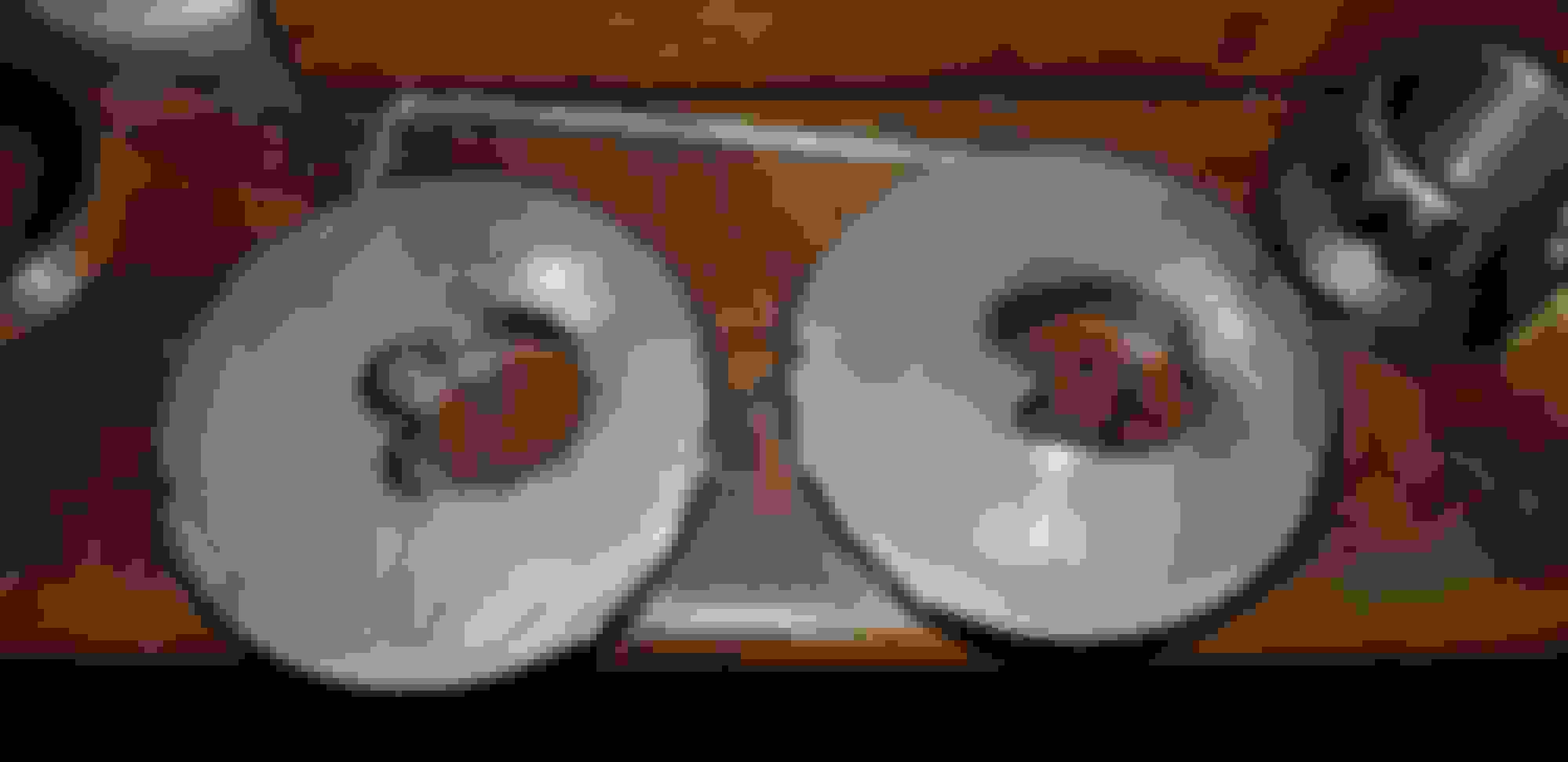
I primed the rotors by just spraying with an aerosol can of kbs high temp zinc, I removed all the rust prior by mostly soaking in wd40 rust remover, but needed a brief muriatic acid hit on the inside front rotor vanes where the soak would not reach. It kind of left an air pocket when they were submerged and it left the rust there.
This is the inside front rotor area that was the most difficult to completely de rust. I zinc phosphate prepped it, there is just a light flash rust in places.
At first I taped off the edges so I would able to get the insides coated without getting too much elsewhere, then removed the tape and came back an sprayed that altogether. I also used small brushes which bent the bristles after a while until I was just mopping it in there, I sprayed a few oz in a jar and brushed from there also. It had a lot of solvent and went on really thin so not much worry with any brush stoke appearance plus most of the parts brushed was on the cast surfaces. I used one whole 12 oz can of aerosol primer for the 4 rotors.
Made this new oven with a stool base (removed the seat) and fit the sheet that the heat guns stick trough into the base and a few eye bolts and a cross bolt to hang two rotors at a time.
Then just cover it with a metal trash can, I am only on low right now and the rotors are seeng 250-350 F, with the upper areas being the hotter parts. I can also add foil to close off some or most of the 2" gap around the bottom to raise the heat further later.
I didn't mask the faces, and want to just either solvent clean it back off there or lightly sand it bare with a fine paper only where the pads will touch, there is a few thousandth wear and lines that will be visible even after more paint coats that I can follow.
Last edited by Justin Bailey; 11-10-2019 at 09:26 PM.
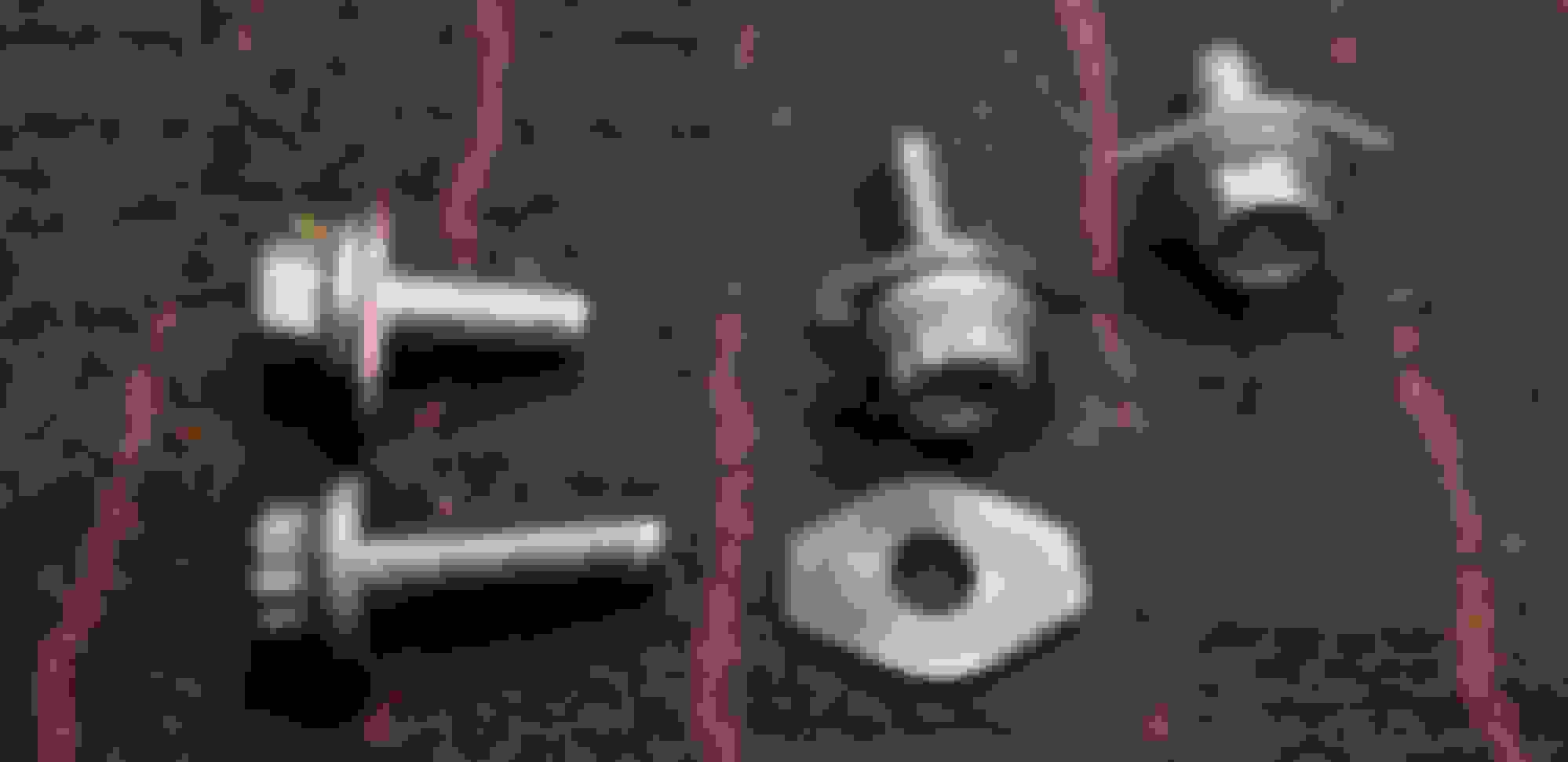
The hub-to-knuckle bolts I had made out of more inconel 718 boeing bolts. They were 9/16-18, had them made into M12-1.25. The front ones are like 40mm long and the rear, 35. I could only get ones long enough for the front in 3-5/8 length so those were cut down. They are all about 23.70mm flange dia., originals are 24mm. We also left as much unthreaded as possible and a close fit to the knuckle holes. I stripped the yellow coating off of the front ones so they matched the bare rear ones with some clr & naval jelly mix for few days, took longer at lower temps. The originals are the bottom two bolts.
Here's the whole set, also the rear hub bearings are painted in a galv/grey color. I used silver grey on the front ones, the rears are a flatter finish, that I kind of like better.
I had to add some thread a little further onto the bolt so used my lathe and filed the appropriate diameter on a portion, and use a die that I dremel split and adjusted in this holder to get the same thread fit but further on the bolt. The kind of dies I am getting for the stainless cutting come unsplit only, and the regular HSS dies won't cut this harder material, so I am splitting my own.
Last edited by Justin Bailey; 11-11-2019 at 10:42 AM.
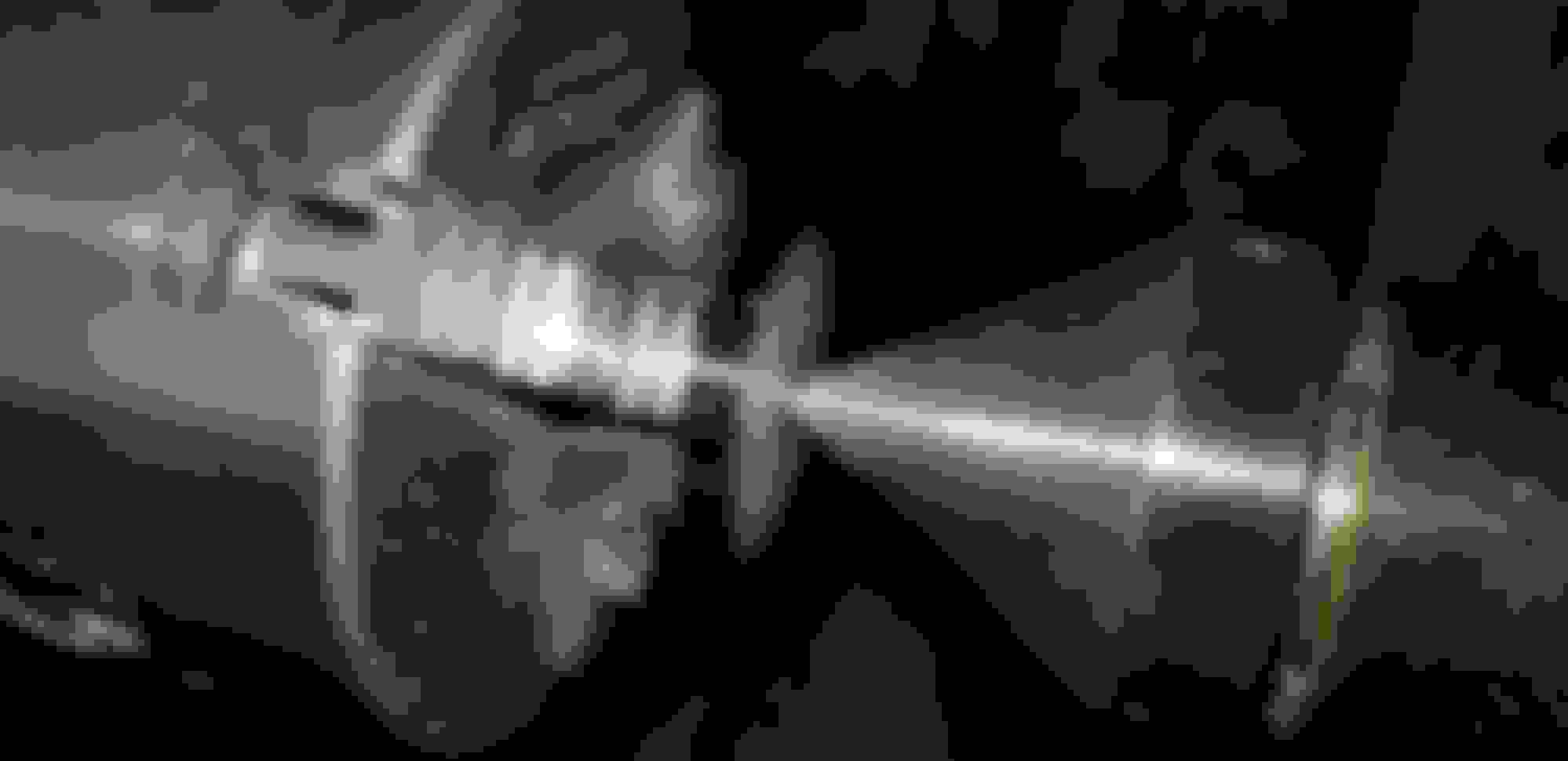
Bought a super cheap stick welder and was trying it out on regular steel, but then got 308 rods and 304 plate and went about testing how strong an Arp stainless bolt will weld to the 304. It was a 1/16 rod and it was a lot easier to strike than the regular steel 6013 rod which required more amperage to get going then went insanely fast and was out of control. This is a few ugly yet strong spots around an M10 bolt tightened in a drilled hole in a 14 gauge piece.
Not sure if I would go with a continuous bead or just a few tacks (3 or 4) spaced out evenly. It seemed to flow into or penetrate both the bolt and the sheet just fine. I need to work on the correct amperage to get it little more controlable.
Tested 50, 75, 100, 125, & 150 lb ft on just the bolt to plate to test that joint and all held, no movement. Then did the same with a nut to see if I there was any considerable strength loss from the heat. There was notable bolt strech like 1/2 mm at 125 lb ft but didn't fail, then the 150 lbs snapped the bolt, blah blah that is normal for this size fastener anyway. Very satisfied. I will be using an M12 size for the camber bolts, so no problem with the strength. The people at ARP advised against it when I asked at first but I explained that I would be only tacking them around the perimeter of the flanges, also helped me decide to get the 308 rods and not the 316 ones. I used some anti seize for the test though so the torque was probably greater than wrench readings.
The caliper says 33.85, it's hard to see in the photo.
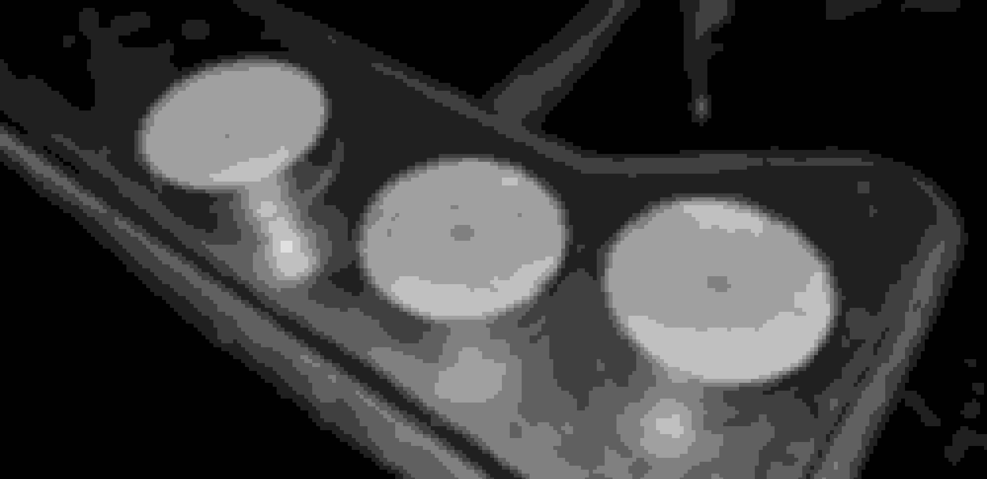
I have a 10 pack of 3/16" thick 304 laser cut circles made to 34mm found on ebay, the originals are like 33.85 or so. Still went and held an original in the vise and tested it out up to 100 ft lb, then 125 spun it from the washer. I found the bolt to be splined and the washer was pressed on, may have also been brazed, I think if I were to try and knurl the bolt it would be fine, but the welding seems much stronger, faster, and cheaper to do for this, so I may just go with a welded attachment only, while trying to maybe get a continuous bead and then file it smooth and uniform so it looks acceptable.
There still is the challenge of machining a groove in the bolt and how to figure out how to uniformly make the hole on the washer with tabs that register into the grooves.
This is an original I tested to failure, you can see faintly that there were splines, but I spun it a little and plowed them off, also seems like there was a posslbe braze going on in addition.
Last edited by Justin Bailey; 11-20-2019 at 08:45 PM.
Figured out a lot I could do with making the cam & toe bolts, particularly the washers.
Got the 10 pack made at 34mm, getting 10 more because I will probably botch a few trying the welding on them.
First center drill to hold them..
So I could pinch them with the live center to polish & chamfer the edges. Final size is 33.90, fits between the sub frame tabs well.
Then figured out if I make an offset split washer I can hold them to drill them with great repeatability and uniformity.
The offset is about 6.5 mm. The big drill just roughed out most of the material but took some fine tuning with a burr in the drill press and lots of looking at the light gap to get it round around the edge of the inside.
The thread end washers I could drill around the perimeter of the holes by using an original as a guide.
Then drill more of the bulk out.
Stacked them with an original again in a drill vise and used a dremel 1/8 size burr but with the smooth part riding against the original, it kind of routed it to the original. Only have these 2 so far, but they fit better then the originals while still being loose enough to slide easily on an orig bolt's grooves.
Also used the jig washer for the washer on the bolt head end.
Will practice weld on a few wrong-threaded m12 bolts first, the hole was 1/64 under 1/2, so 31/64. The bolts I will use will be reduced and cut from 1/2-20 bolts and threaded 1.25 pitch and kind of pressed on and welded.
You can't buy M12 -1.25 ARP stainless, so I have to make my own from cut off 1/2 ones, which are available up to 6" and with a max 4.75" unthreaded part to work with, just made to use a 9/16" socket or wrench on the bolt head since it's standard, but found a 12 point 14mm socket will also fit very well, though my 14mm 12 point wrench is a bit too tight.
Might make some adjustment marking lines like the original somehow.
Last edited by Justin Bailey; 03-08-2020 at 11:19 PM.

 10-07-2019, 03:19 PM