When you click on links to various merchants on this site and make a purchase, this can result in this site earning a commission. Affiliate programs and affiliations include, but are not limited to, the eBay Partner Network.
Hello & welcome to this guide. If you’re here, it’s because you have had the idea or question, “how do you MT swap a G?” or “is it possible?”. The obvious answer is yes, and many people will say “if you have the $ anything is possible.” While that is true, I tried to be as cost effective but also did not want to cheap out (More on this later). This is my daily and is going to morph into a track build, so reliability is a must and I want to do it right the first time. There is a lot of info on the 370z forums as it is a more common swap, and it is better documented than on the G community. Nowadays, everyone wants a VR trans swap, but I like to think that the performance gain of a better AT hides the skill and talent of the driver with a MT. When I first researched this topic there was no info or videos just here say. When I finished the project in July of 2023, I was surprised that there are 2 videos on YouTube. 1 had no real substance whatsoever and the other one was better, but ok, I guess. (Maybe I will make a video essay on it in the future.)
Special shoutouts to Z34Hakeem, a member of the 370z forums who has done a swap on his z and documented it which the majority of my research and walkthrough was based on, to Max2011, a member here on our forum and a friend in my area who sent me pics for reference points, to TxBoostLife, a youtuber who has the hands down best video of MT swapping a 370z as well as MT swapping a q50 with the VR30 motor, The Carizon, another youtuber who has a detailed videos of MT trans maintenance & finally VQ.Unvie a member of another VQ forum and friend that came by and let me take apart his center console and take measurements as reference points.
While this is as close to a definitive guide as I could make if anyone goes through with this and finds a more efficient way to do this (inb4 the “just sell and buy a manual comment”) please feel free to share. If you have any questions, you can always message me on IG @ Code_Blue_VQ.
First thing, I am no mechanic but have a basic understanding of things. Growing up around cars & fiddling with small things has helped but I work in healthcare, so this conversion was not in my comfort zone. I had A LOT of people doubt my ability or competence at the task at hand, with almost everyone saying, “just sell it and get a BMW”, “Take it to a shop”, “Just put in a used 5 AT and sell it” etc. I did have a small circle of supporters esp. my wife so kudos to her for helping as well as for helping me spin a wrench even though she didn’t want to. With that said, I am not responsible or liable if you go ahead and try this on your own and things do not work out. There is no specific order of operations to get this done in. I did some things while waiting for parts or during inclement weather.
Now, time to begin…
Cutting the brake pedal
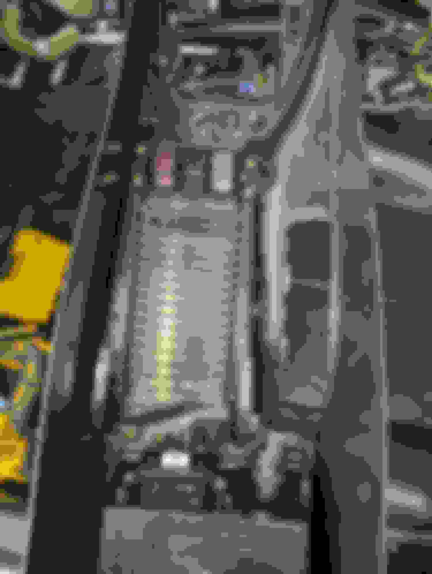
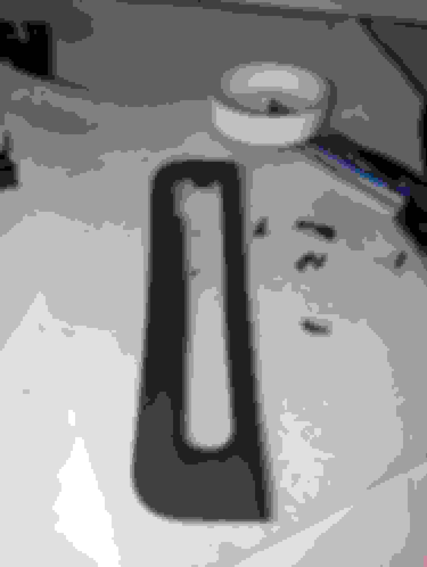
This is probably one of the easiest jobs and where the surgery begins. Remove the pedal cover from a manual pedal and tape an index card (or cardboard) on it and trace an outline and then cut. You now have the pedal size since it is the only difference between an auto and a manual pedal. Remove the auto boot, and then line up the cutout to the pedal. You will notice that the upper left corner of the pedal is in line with the rod that the pedal is welded to. Using a bright color sharpie trace out the template and cut it with an angle grinder. When done, you should file down all the sharp edges and hit it with some paint just so it doesn’t rust. Once dry put the brake boot on and your golden.
Use A Template to find your spot. Reference point. Clean it up. Make note of the location of the upper left corner and the arm of the pedal. Use some lube to help slide on the pedal.
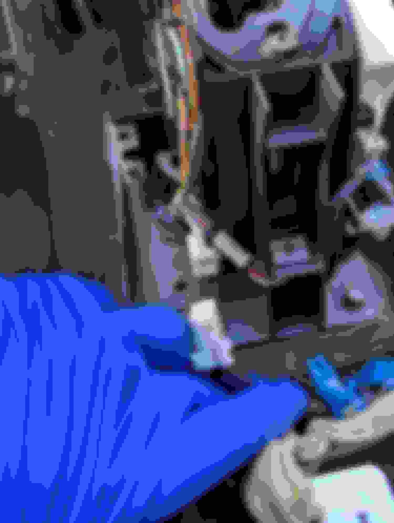
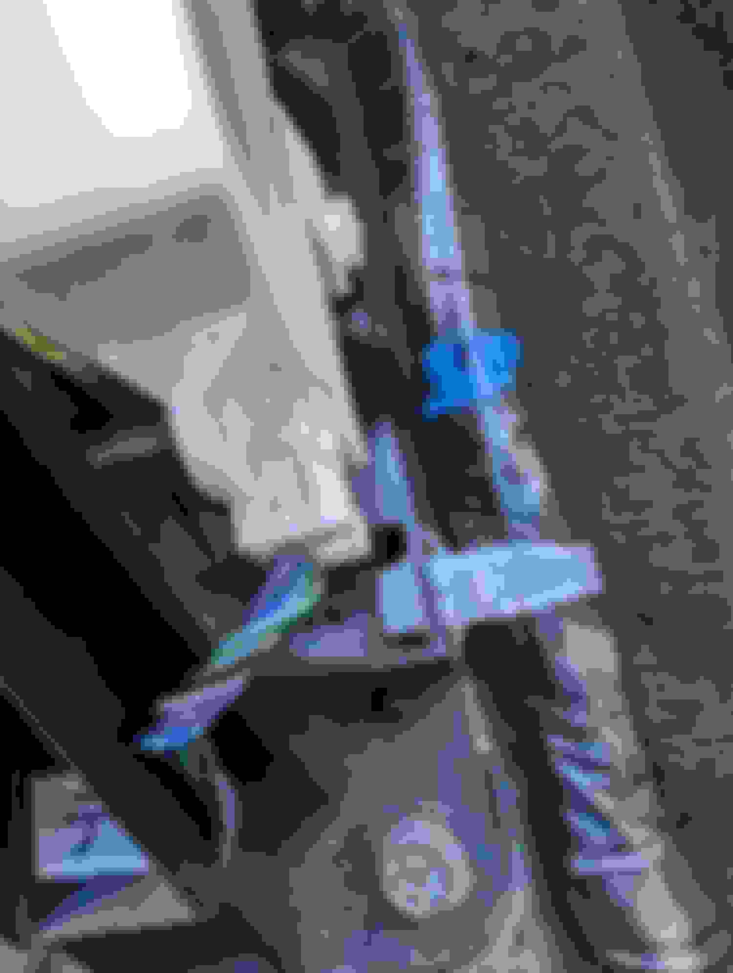
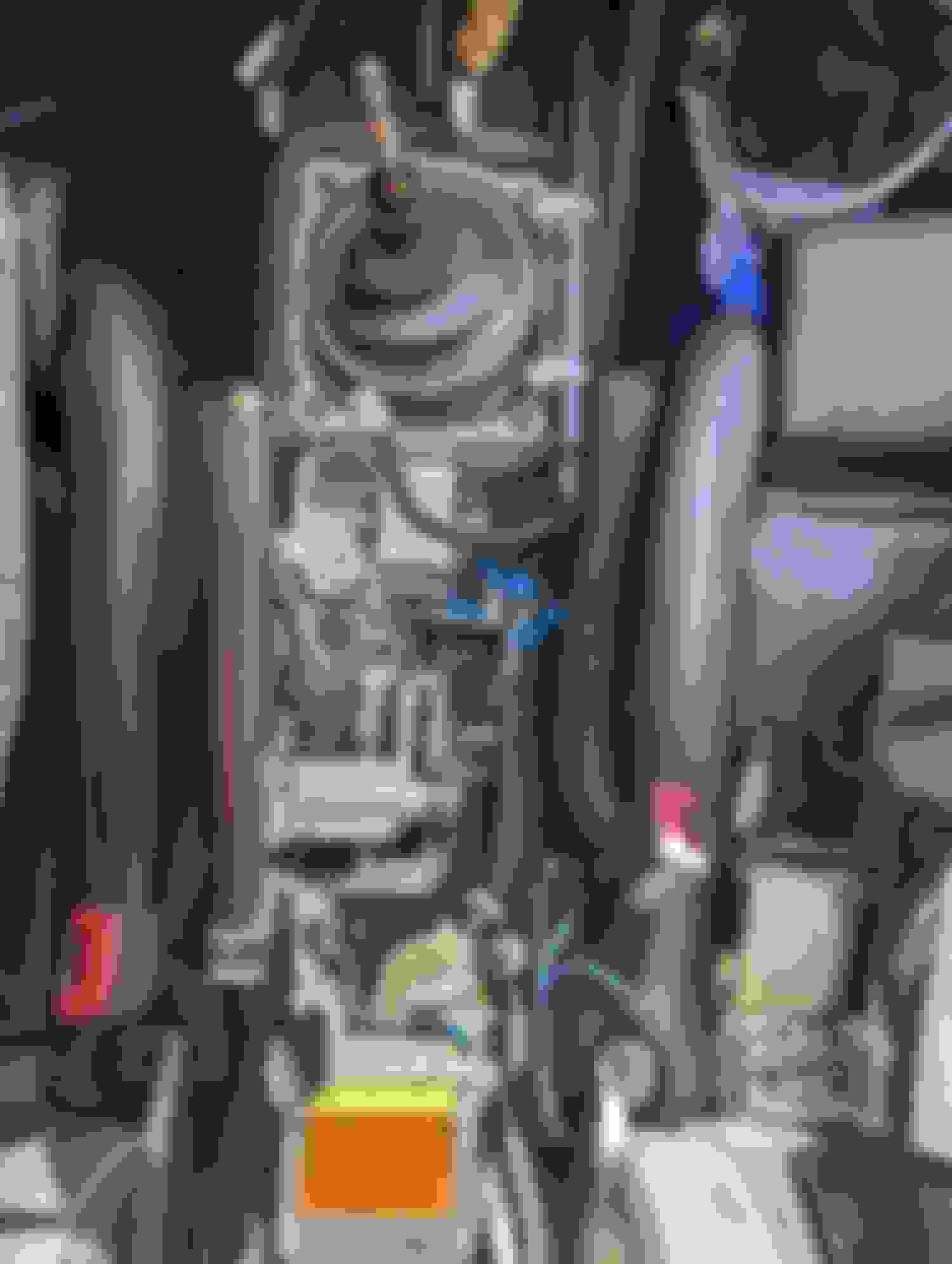
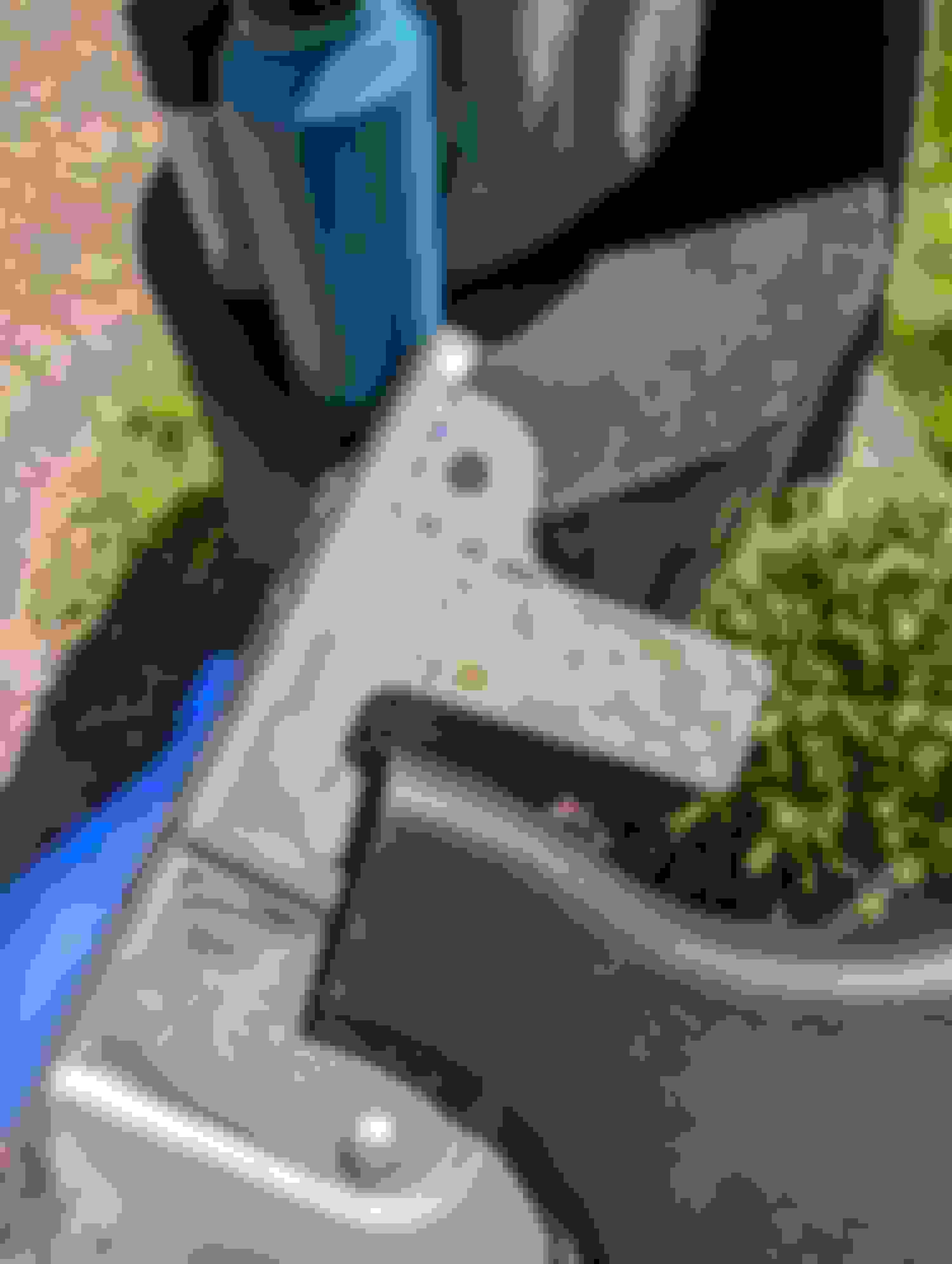
Removing the Foot E-Brake/Cable
This foot pedal (technically they are all foot pedals) lives on the left side of the foot well just below the hood latch. There are four 12mm bolts that hold on to the foot pedal parking brake as well as a small 2 pin connector attached up top. The bottom two are very easy to remove with a deep socket. The top right one is a little tricky but with a small handle ratchet and a deep 12mm socket it is doable. For the trickiest of bolts being the top left side, you need to go over the top of the pedal as there is not enough room to go at it from the front. Unlike those swapping the trans in a 370z it must be removed as there isn’t enough space for the manual pedal if you leave this behind.
Its best to remove the cable from the pedal as it makes keeping the space clear easier. A deep 10mm socket will do the trick. You can use a heavy duty needle nose pliers or a thin flat head to remove the clip that holds the cable to the pedal. I was surprised that the pedal felt heavy. Now that it is clear, you need to pull the plastic push pins (2 of them) that hold the carpet on the driver side foot well and you will see that there are two 10mm nuts on a bracket.
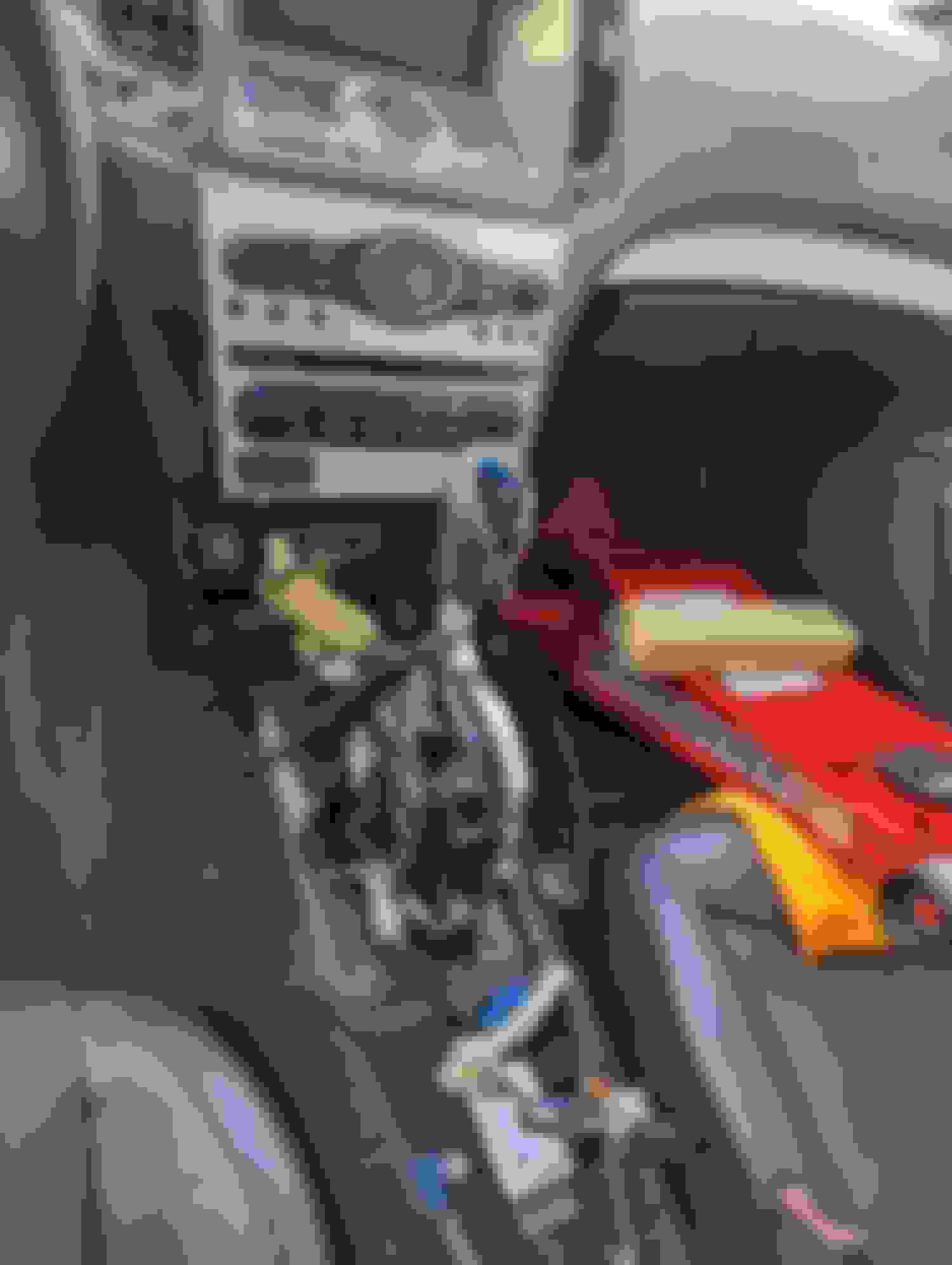
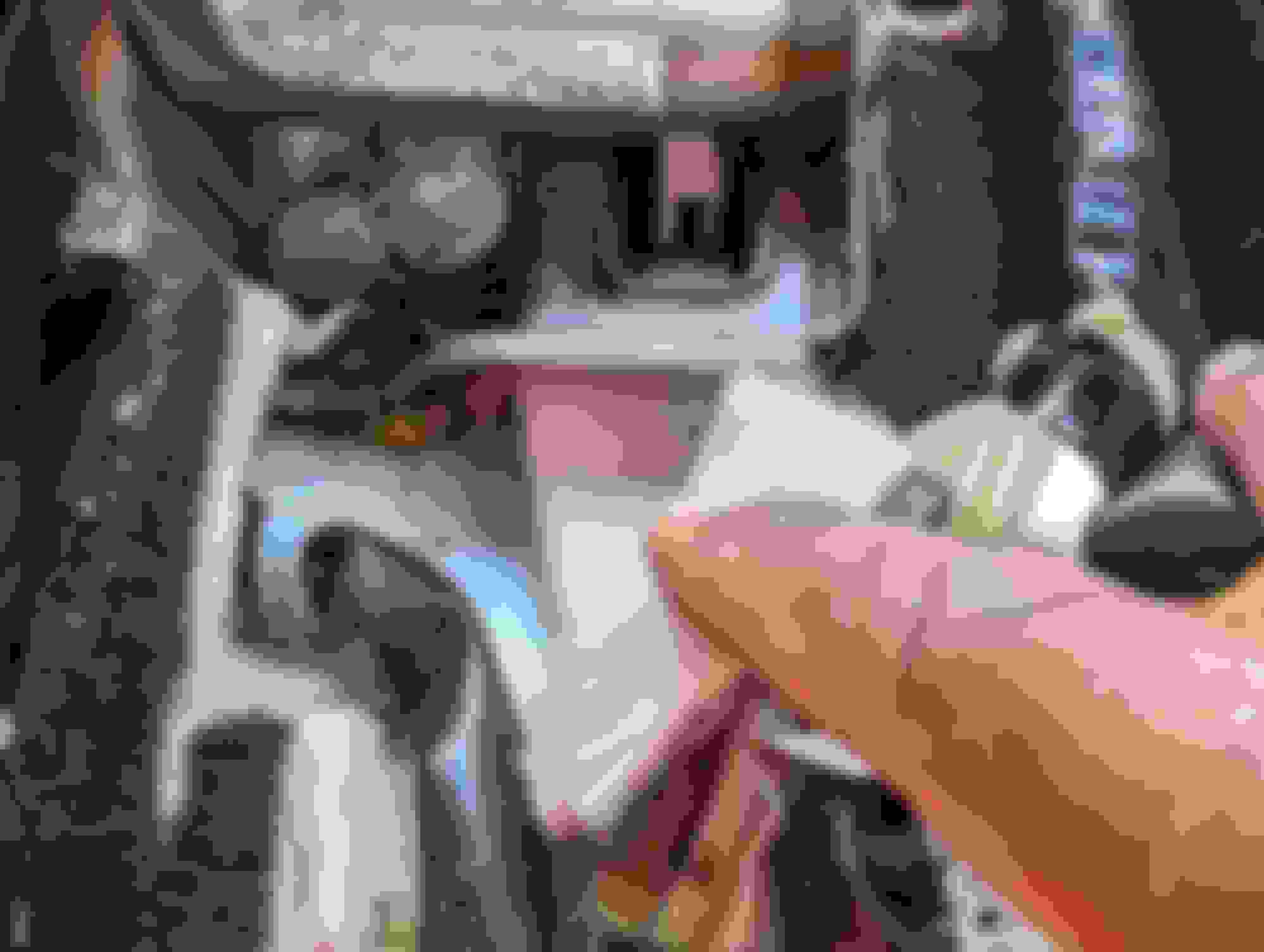
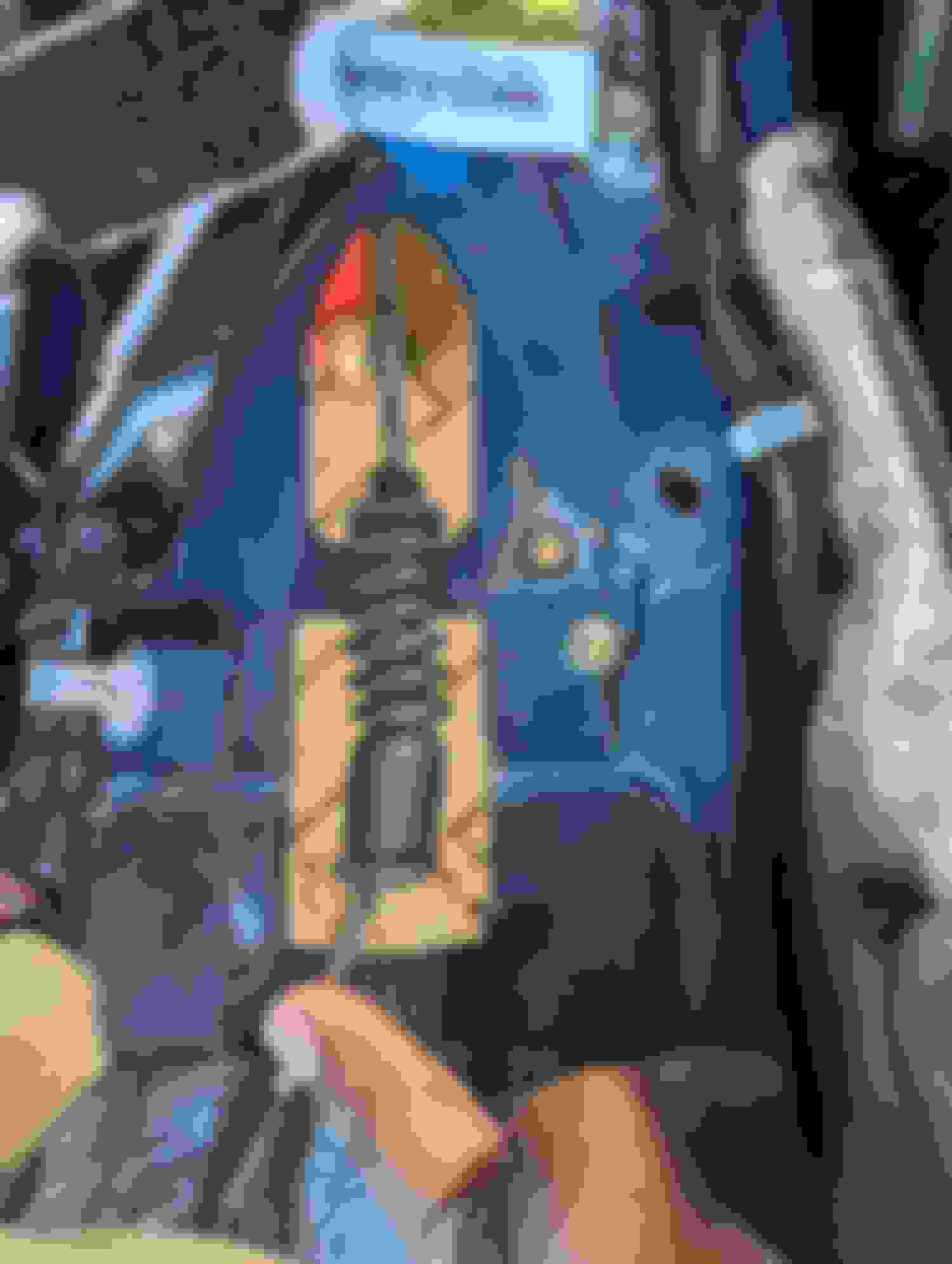
There is also a 10mm behind the gas pedal which is secured with a tab that has a notch on it. (Now remember when I said trickiest bolt. This one maybe it. You do not need to take off the drivers pedal but you can push it gently to make room. If you have the driver’s seat out it may afford you more room in the car to work but I had mine in still as I still drove the car around until I was ready to swap everything. Another thing that would make it easier is if you already cut the brake pedal and put the cover on. I did this on mine but forgot to put the pedal cover on and so I was cut with some shrapnel I didn’t file down smoothly enough)
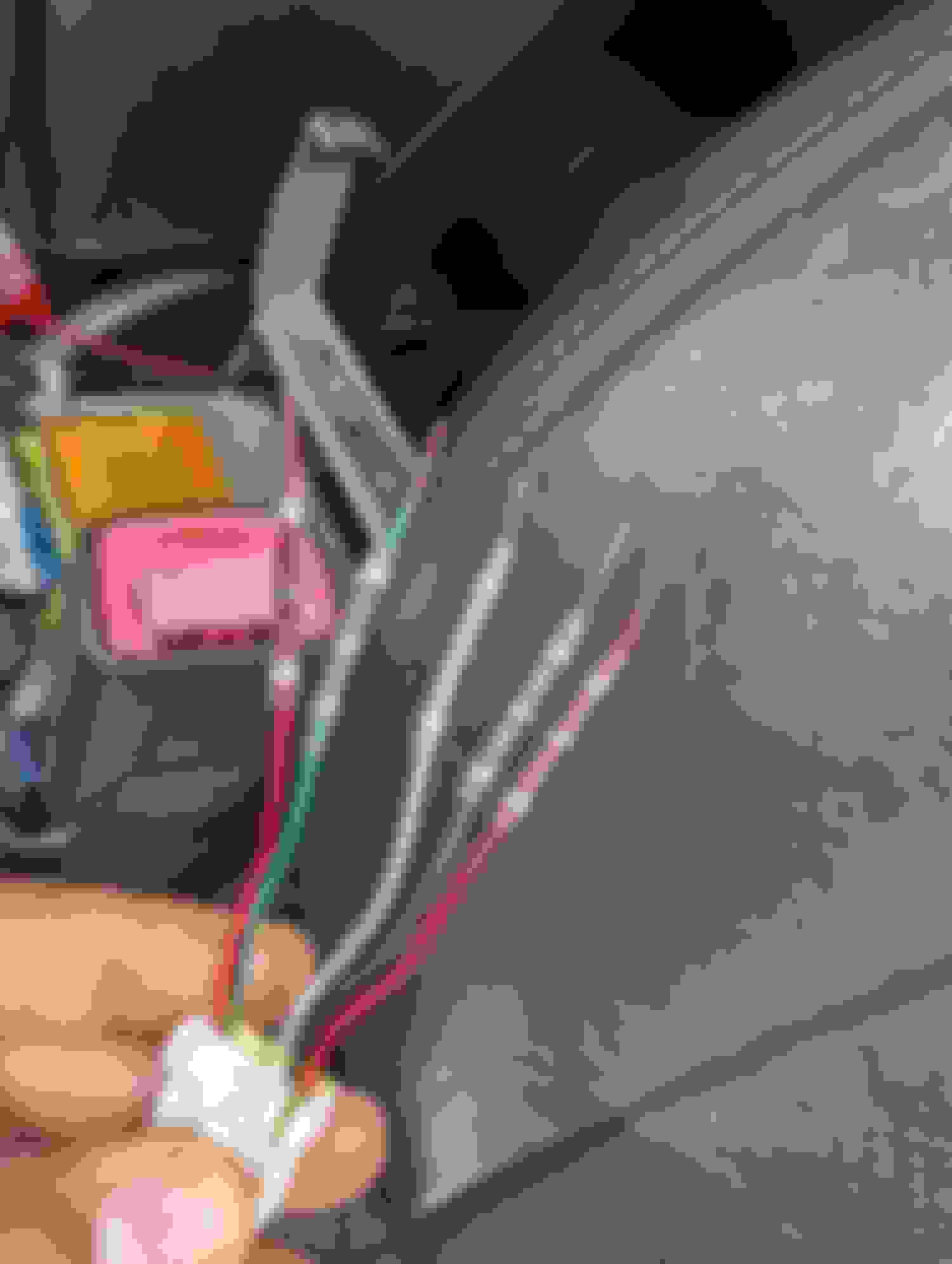
Easiest way to deal with this is to use a long thin 10mm ratchet wrench and then you can unscrew it hand. Then using a long flathead, go over the gas pedal behind the brake pedal and put it up against the notch and push towards the pedal. It should give just enough clearance to move to notch over so that you can remove that tab. Now carefully route the hand brake cable through the back of the gas pedal being careful with the wires behind it and let it sit on the floor in front of the gas pedal.
For the second tab with two 10mm, an extension and a swivel socket will help as you angle it and pull the carpet away from the center console area. I found it easy to jut cut the tab as short as possible with a grinder or Dremel, so that you can route the remainder of the cable behind the spaces of the tabs that hold the centers console in place. If done correctly you can have the majority of the cable in the footwell free of the console area.
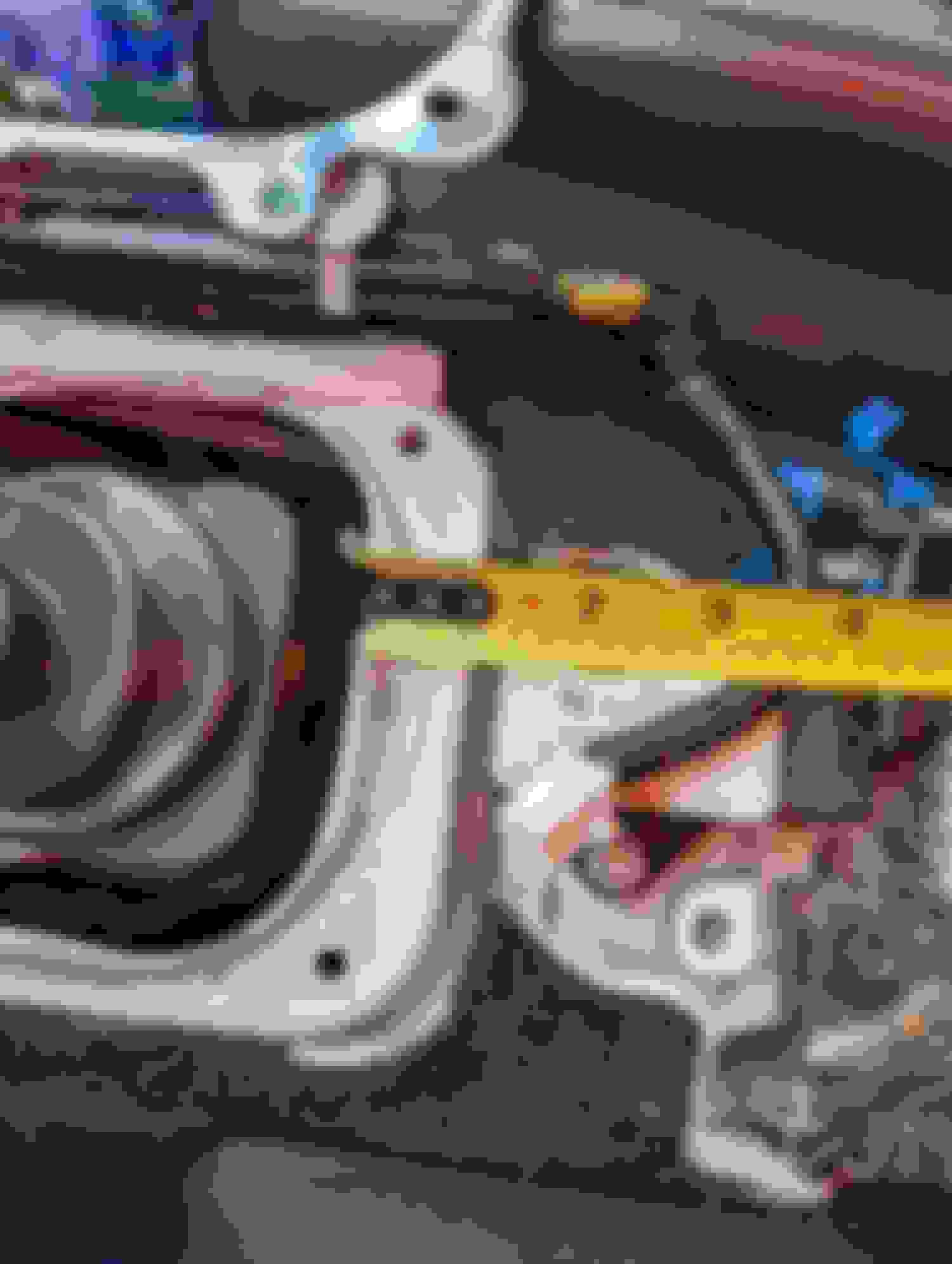
Now game time decision. You can follow the rest of the cable and cut the carpet to release it, or you could have removed the seat and access the carpet and peel it back. Personally, I cut the carpet saving time for myself with a box cutter and will rejoin it later. There is also a curved tab that helps to hold the cable on the center console, which the cable can be pulled out of. Lastly there are two 12 mm bolts that hold it in place to the body of the car via a plate that lets the cable continue out of the car. Save this plate for later. It is next to the air bag module and you should remove it to have more space to work with. Once you remove that plate you can swing the whole cable into the passenger side and get it out of the way. Easiest 2 nuts. Remove the clip for the BRAKE light (extend it for the new handbrake) Remove the 2 nuts behind and the nut holding the cable. Unclip this. (Save for Later) Cable bolt behind pedal. (Not the blue stud) Push the bracket up and the tab wont let it pull forward. Bracket with 2 Nuts under side panels of center console. (Left of the bracket with 3 nuts) Pry upward to make room for the cable to slide out under. Place it to the side and Unbolt the cover. New Space Ready.
Last edited by BxG3?; 09-02-2023 at 01:23 AM.
Reason: Removing no post sign before all parts were uploaded.
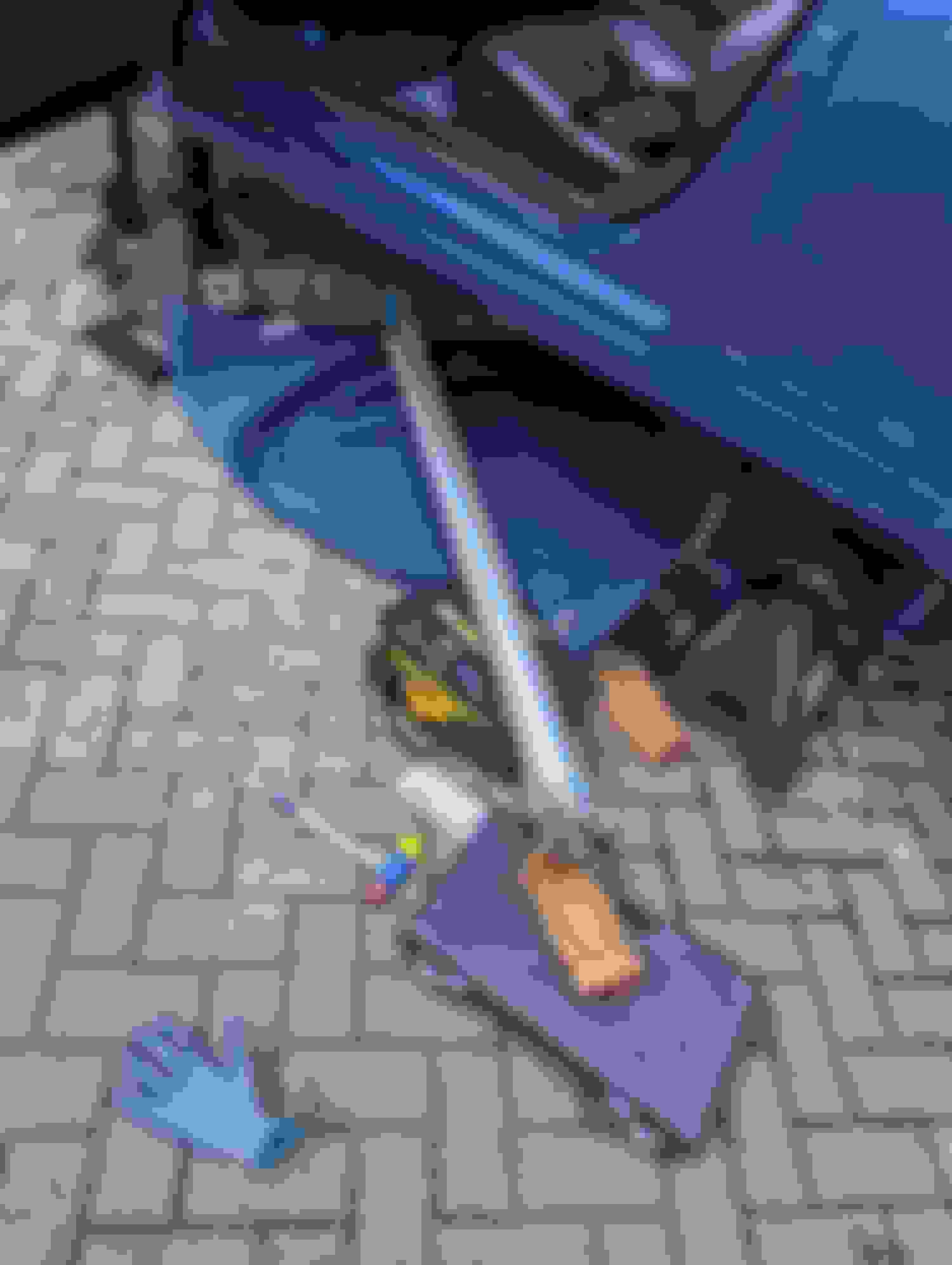
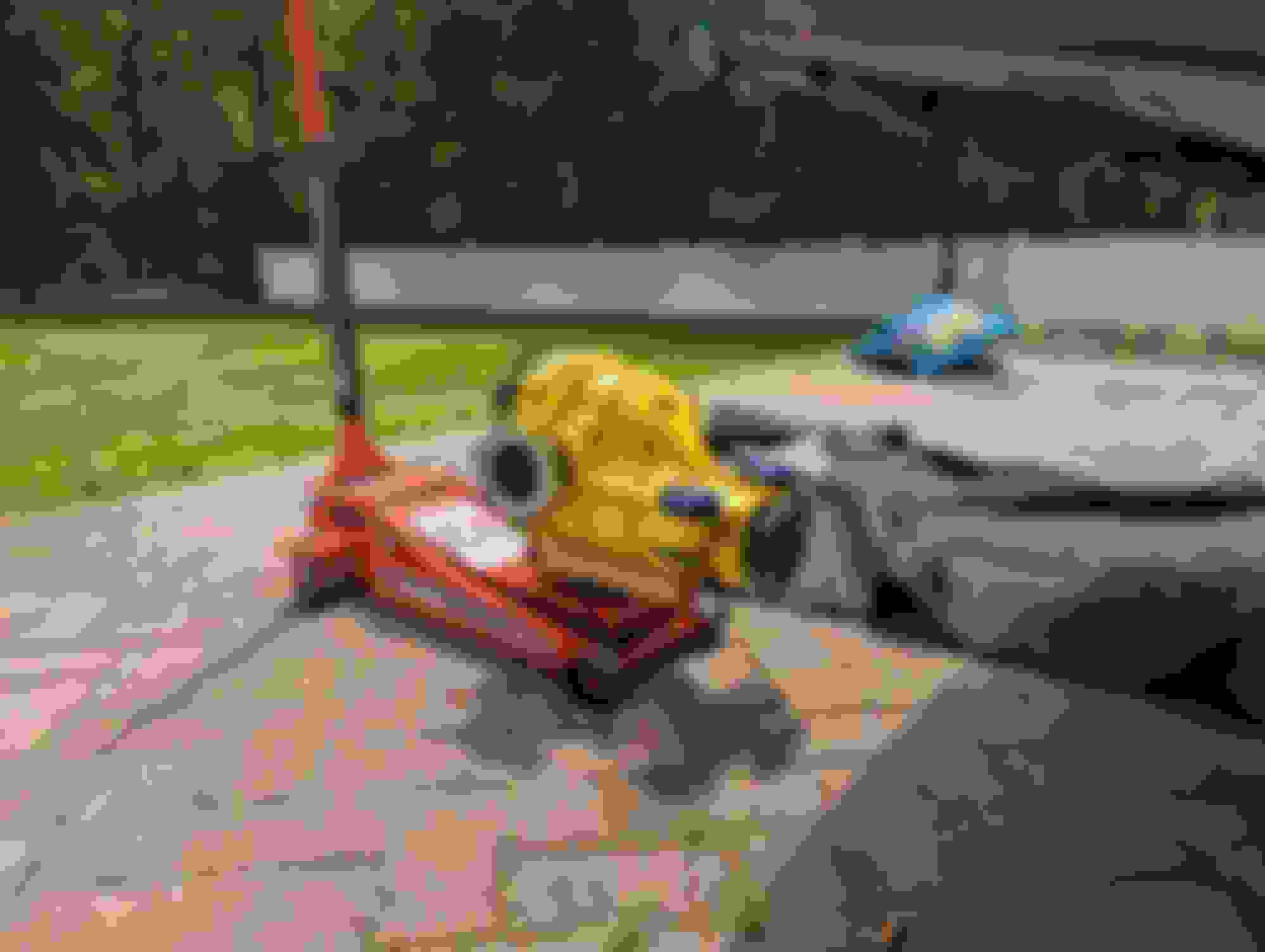
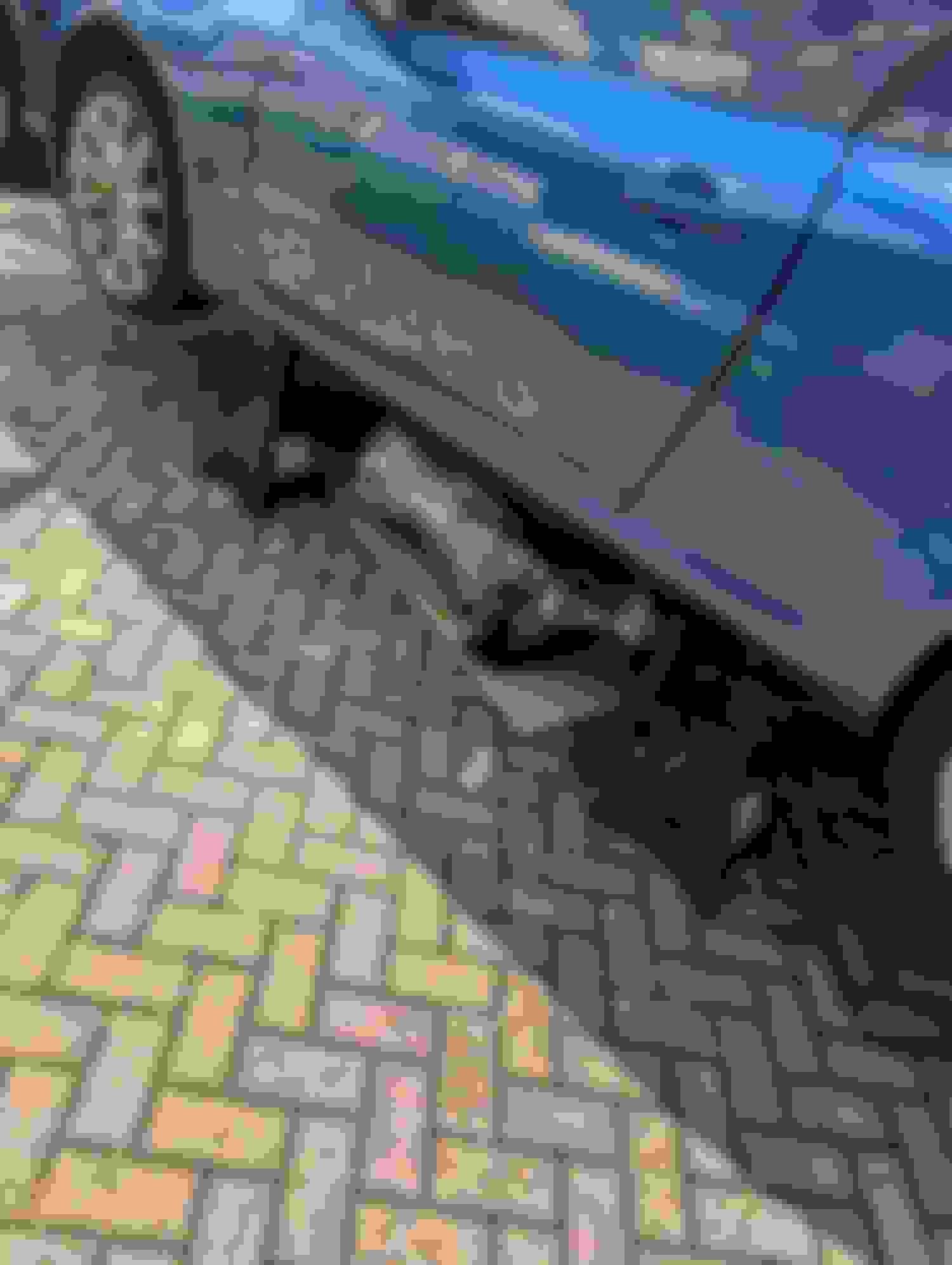
Removing the Remainder of the E-Brake Line & The Driveshaft
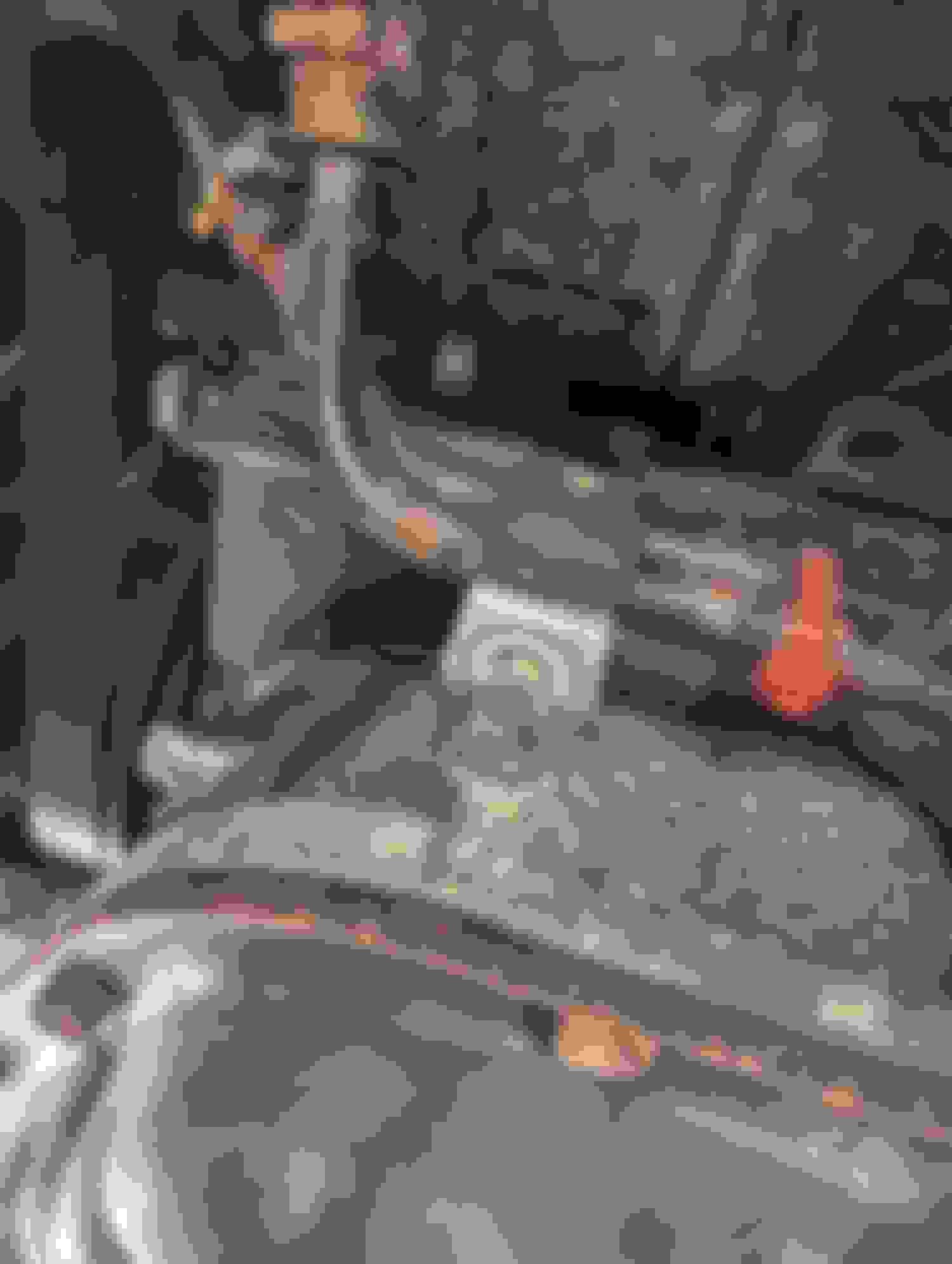
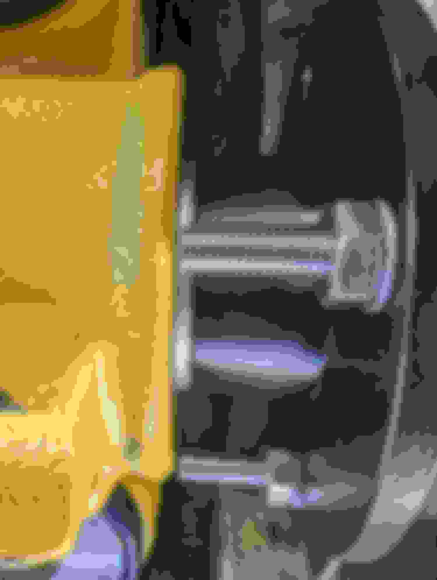
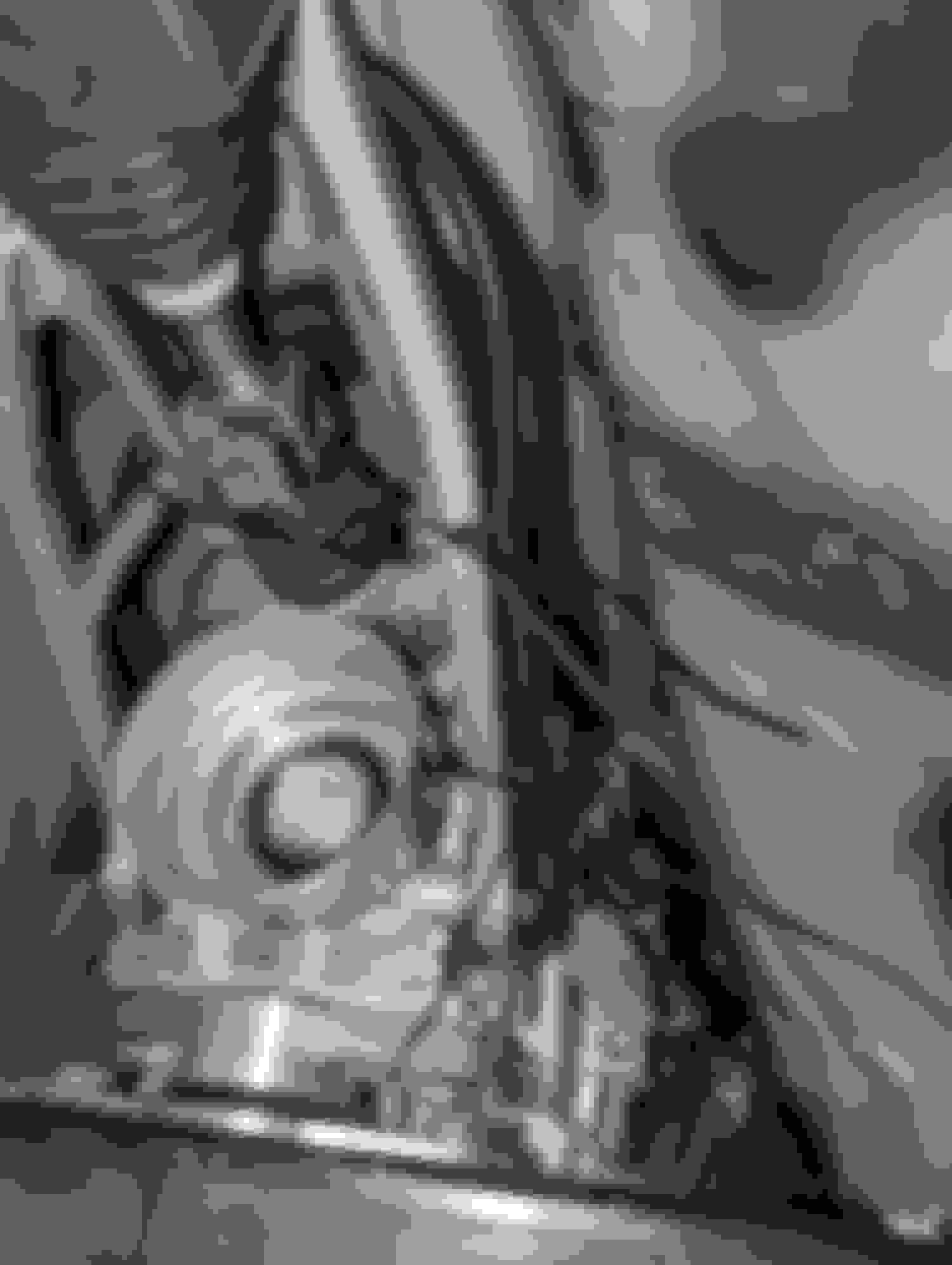
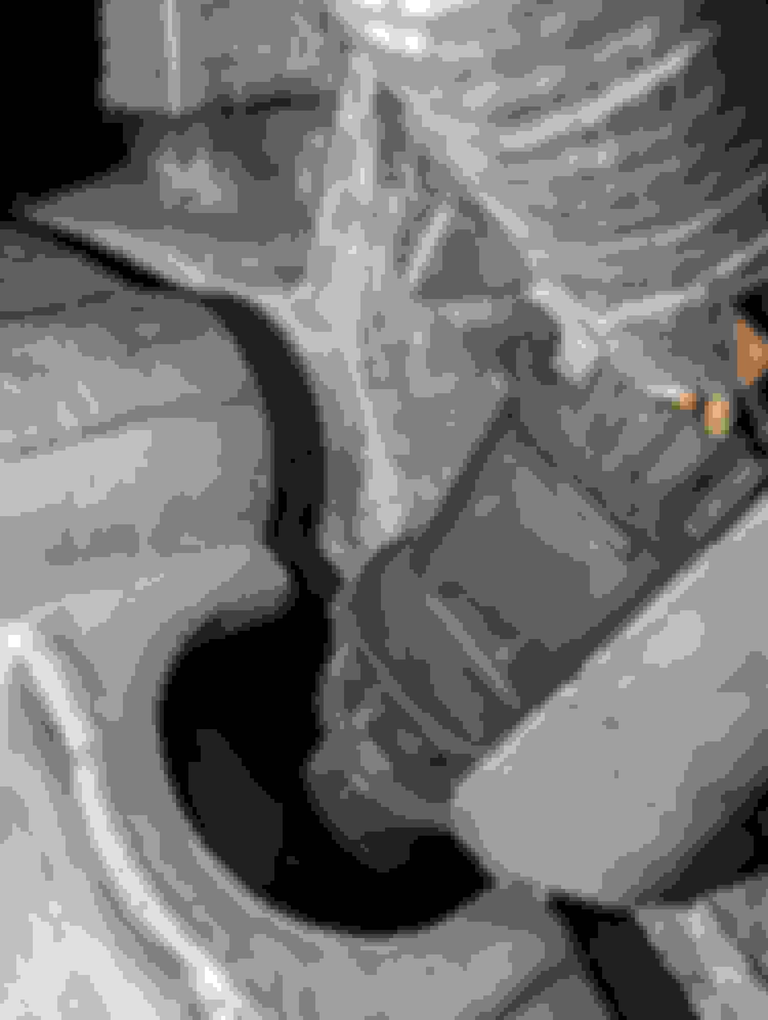
With the majority of the line in the passenger foot well, it is easy to remove the rest of it to make way for the new handbrake. With the car in the air, you need to remove the 2 heat shields, the driveshaft and the exhaust. I removed my exhaust from the test pipe/cats back. As for the driveshaft it is heavy. From the differential side, it’s three 17mm nuts and three 19MM bolts to remove. There are two 14mm bolts holding the bracket at the midpoint of the driveshaft (driveshaft bushing). I used some PB blaster as I live in the dreaded Northeast and had to battle with some bolts. Heat is always your friend but when in doubt, cut it out. I rather spend money on new and proper hardware anyway.
You need to slide the driveshaft forward into the trans so that you can get some wiggle room. There might be some slight fluid leaking from the transmission in the back but nothing major. Just keep a rag handy. When all the bolts are loose, lightly push the driveshaft forward from the diff. You will notice that the nut and rod from the differential flange is extended into the driveshaft. As the middle flexes if give you more room to clear the rod and remove the DS from the back.
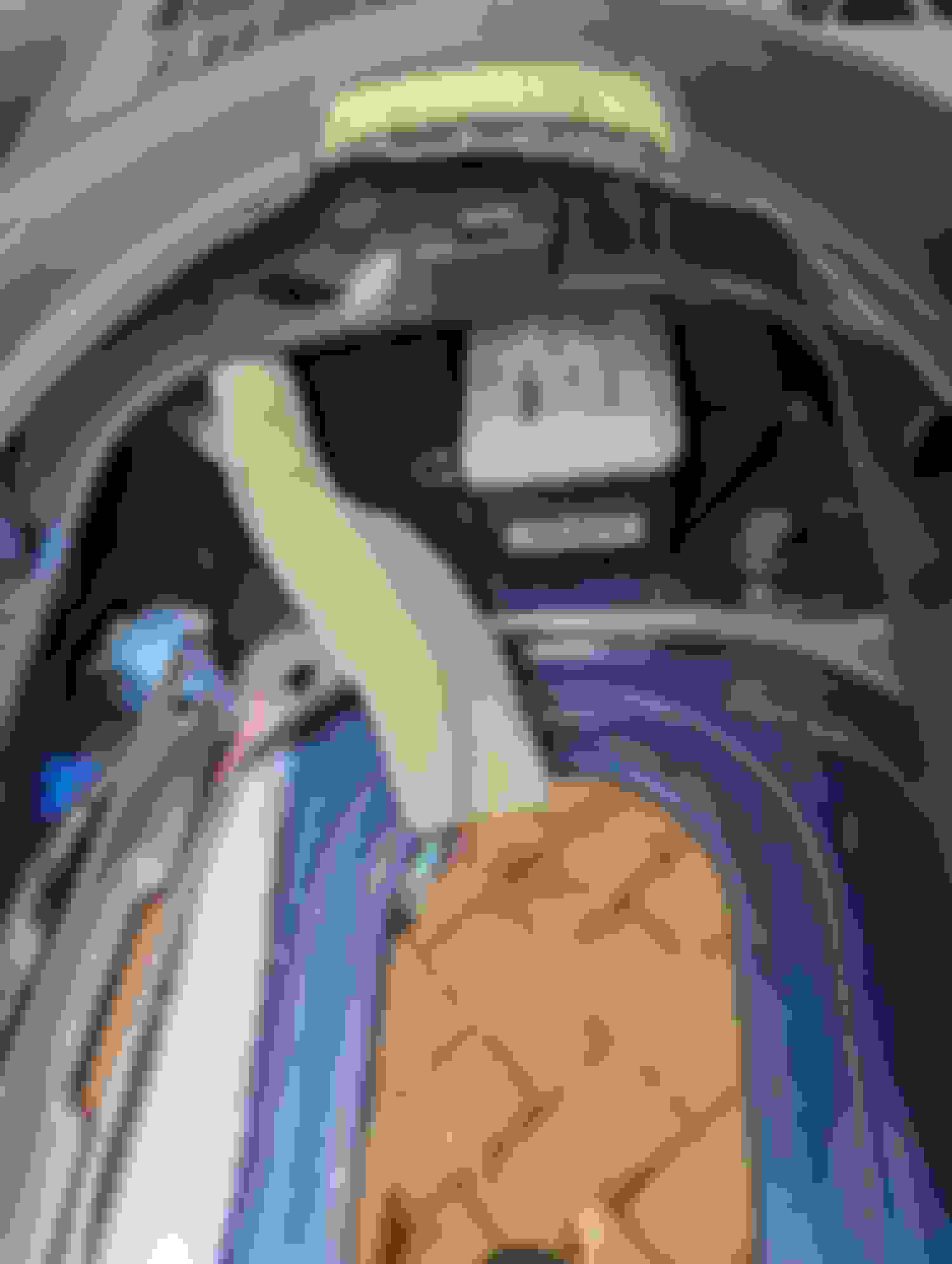
With those things out of the way, you can remove the remaining shields. Six 10mm bolts in total. You will see the cable from where it runs into the car. There is a rubber/nylon grommet to pull out and on the bracket, there is a spring. Remove the spring, and spray some wd40 on the bracket. You can remove the cable by rotating it back and forth and sliding the cable through the notches. If you need more space to do this, you can unfasten the 12MM nuts holding the individual lines to get more room.
6 To Remove 2 Nuts for the Bushing midway. Push forward and down for clearance to remove. Remove the spring from the hook. Push the bushing out to the side. Some PB Blaster & a Flathead to wiggle Free and Remove it.
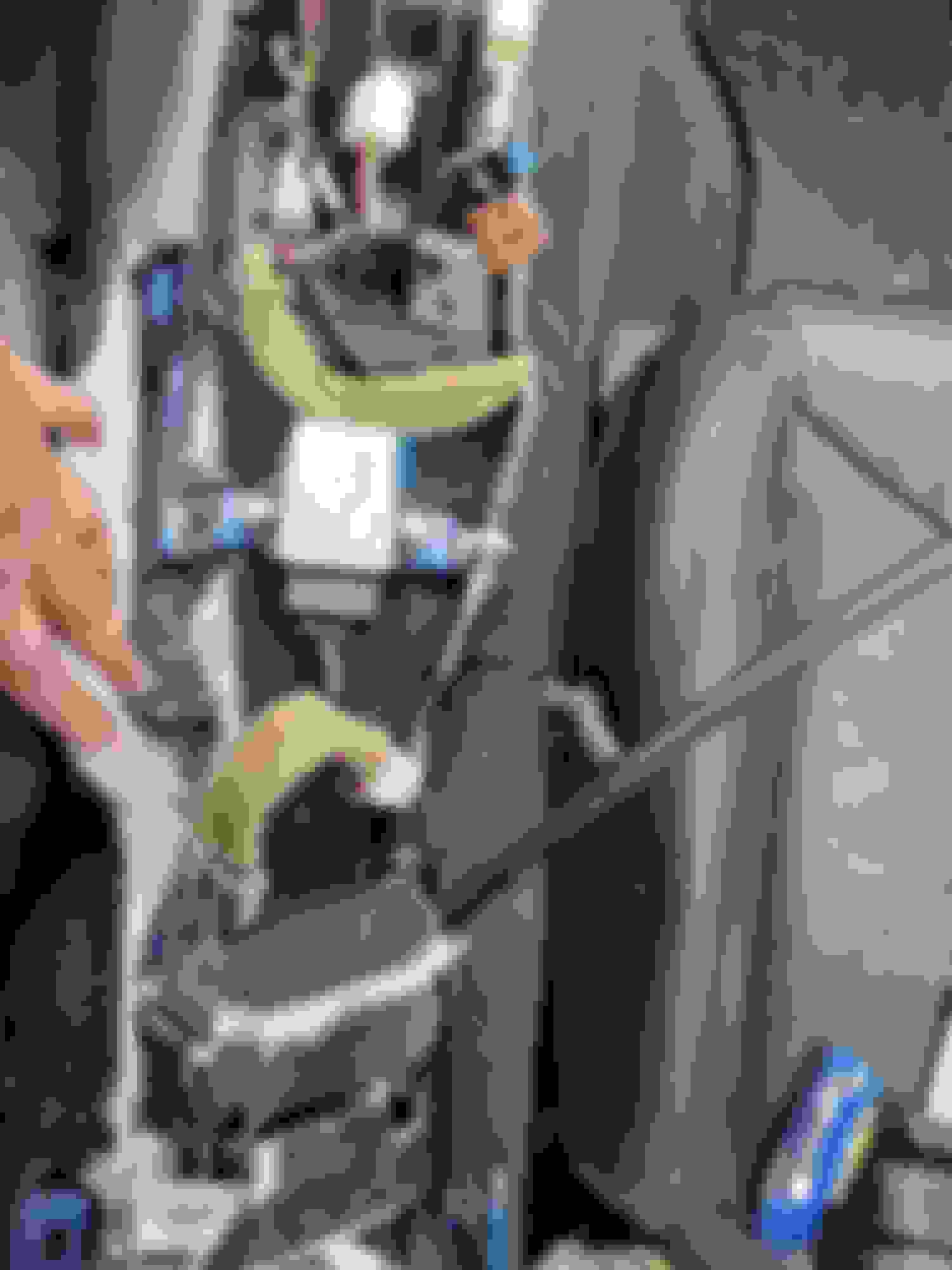
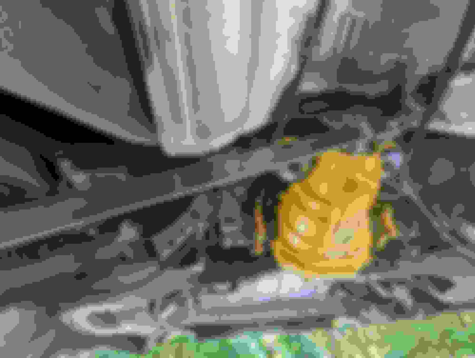
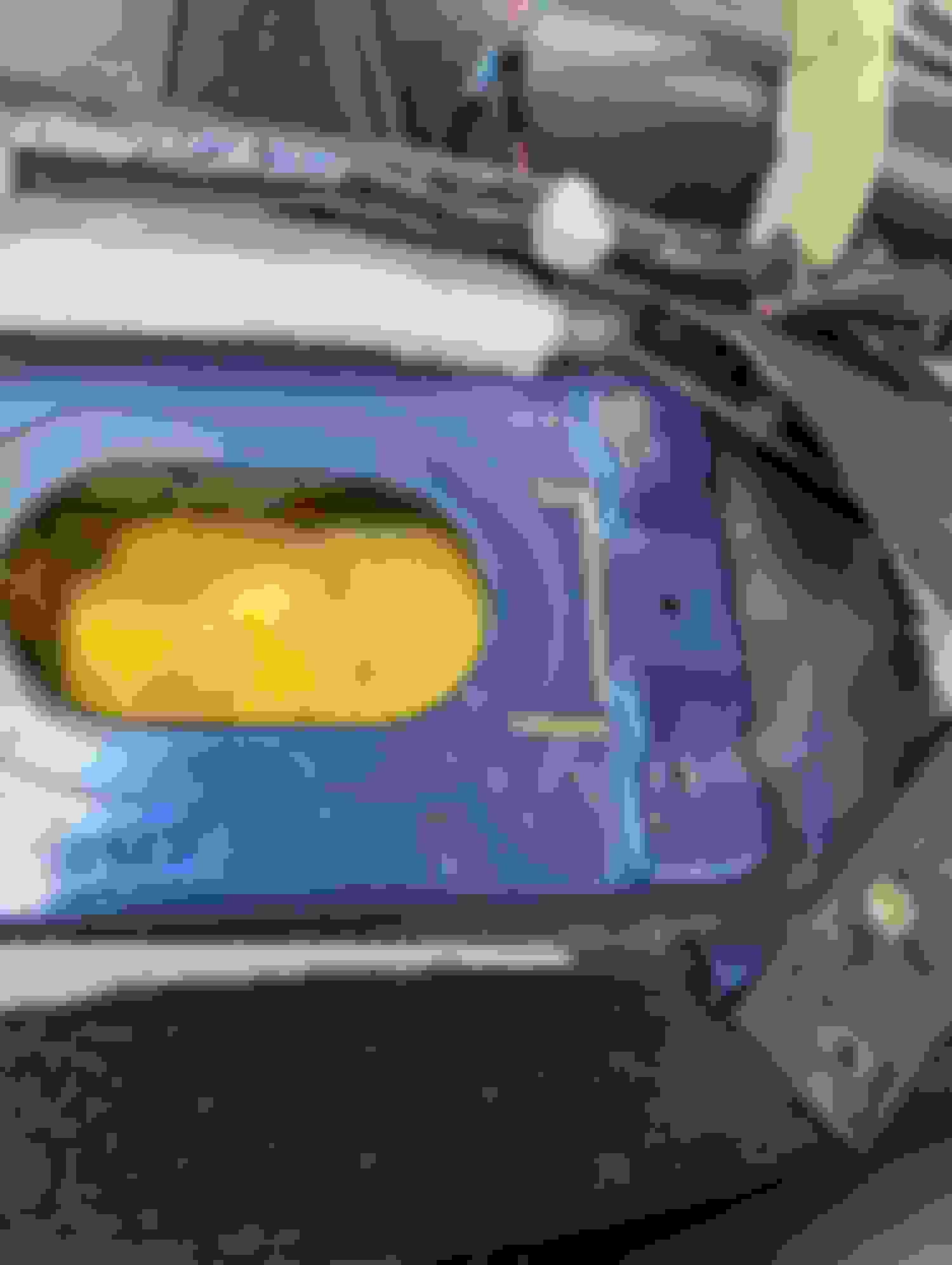
Removing the Differential
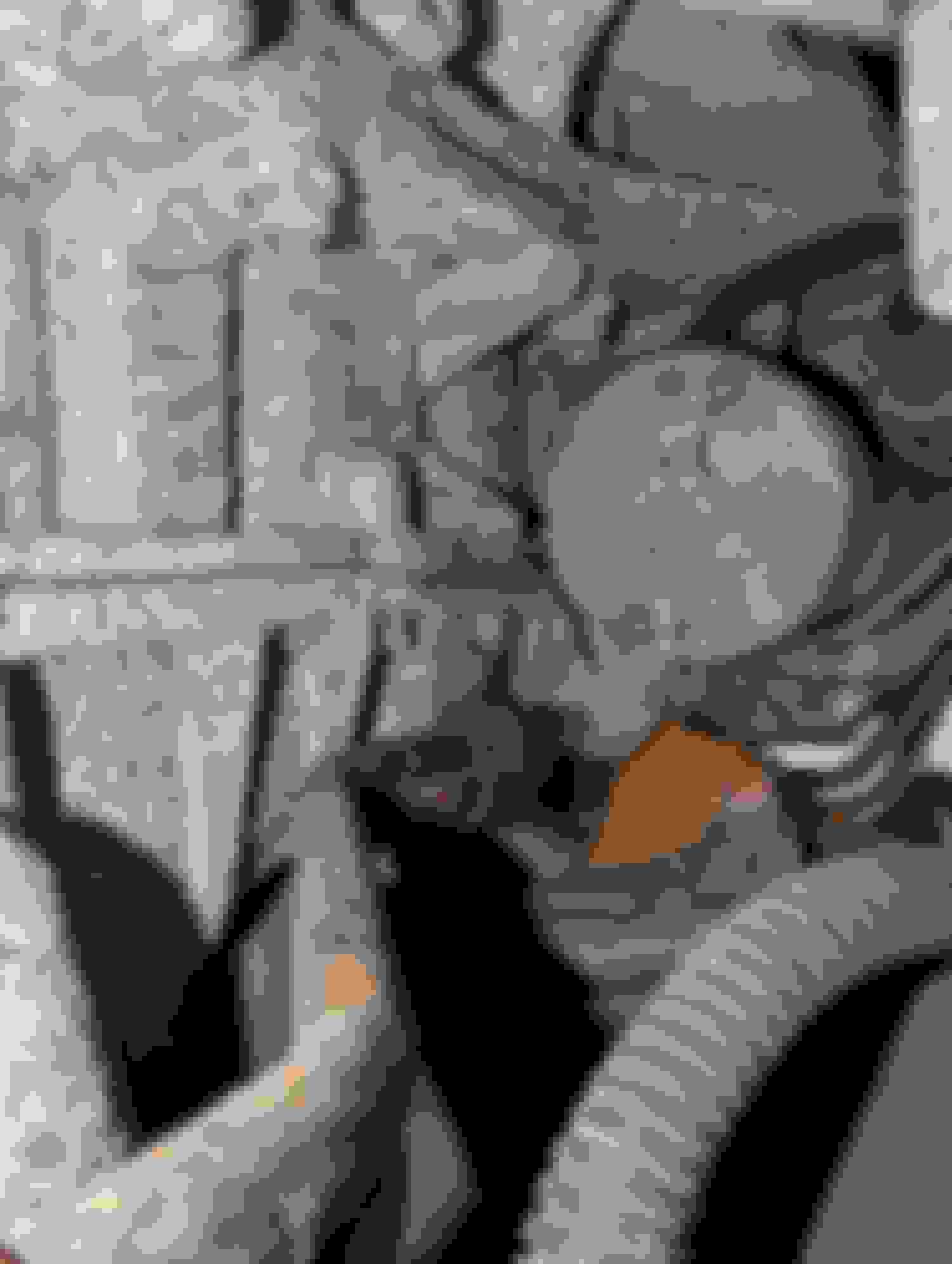
This one is straight forward. Before removal make sure you drain the differential as it would make it less heavy and easier to manage when pulling it and lowering it from the vehicle. Remove the driveshaft & then remove the rear sway bar if not done so already (four 14mm nuts & the end links). You need to then remove the twelve 14mm bolts from both axles (6 a side). I supported the axles with small bungee cords to the control arms to help keep them from sagging. Once that is out of the way, you can use a 17mm for the two bolts that hold up the front and a 17mm to remove the nut from the rear.
I used a jack and a block of wood to help balance, maneuver and release the differential from its place. Remember to undo the two 12mm to remover the abs sensors from the diff before you begin to drop the diff. If not you could potentially damage the sensor. Also remember to remove the breather hose from the top of the differential as you slowly lower it away from the car. Using a needle nose pliers can help with aiding in removing the breather hose. Just don’t squeeze too hard or you could damage the hose or kink the breather tube.
Undo the abs sensors and the breather hose. Remove these two as well as the nut in back 6 per side to remove Push forward to release and then bring it down. Bungies ready to hold up the axles. Yo Ho Ho & a Bottle of Rum
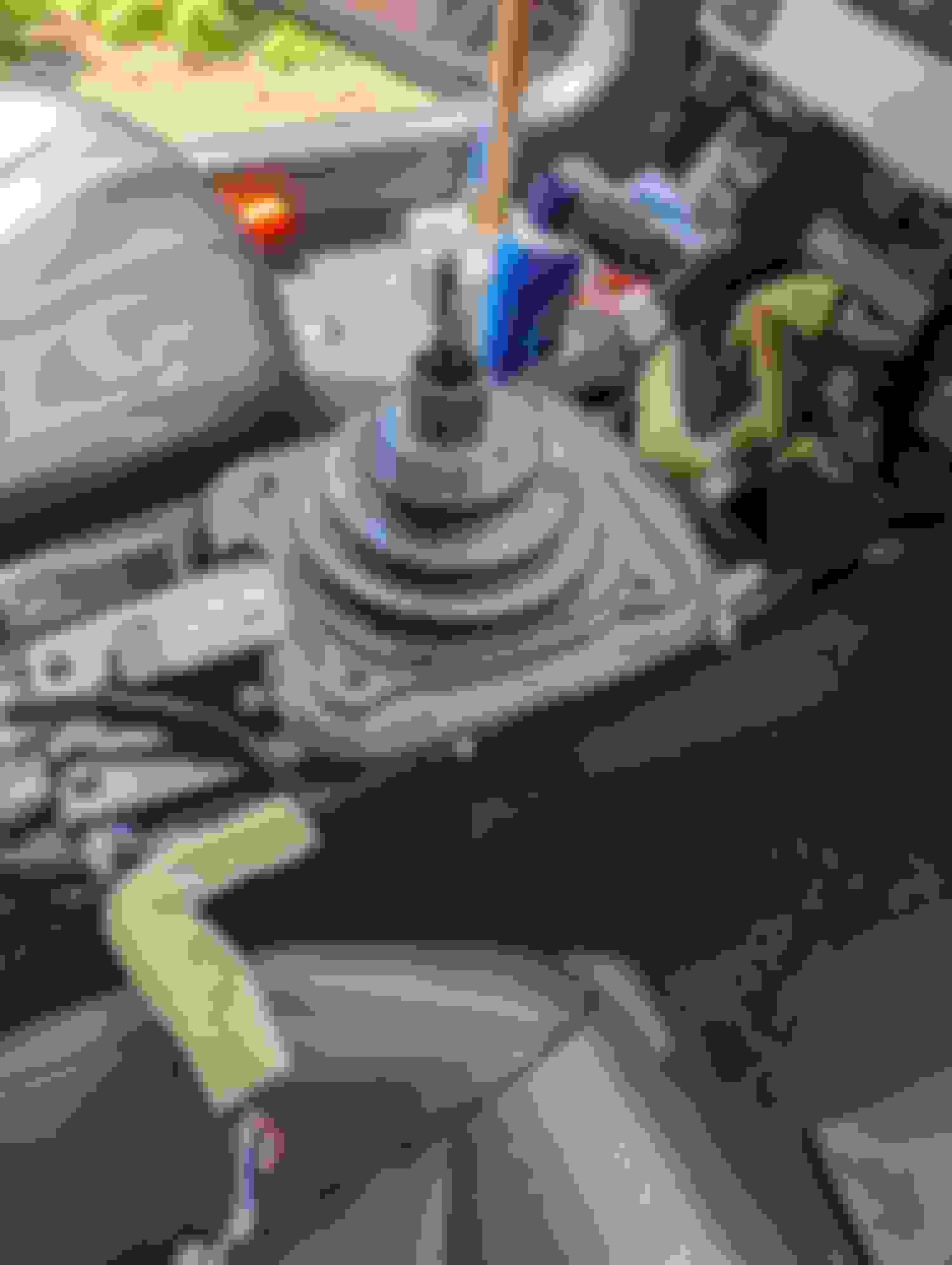
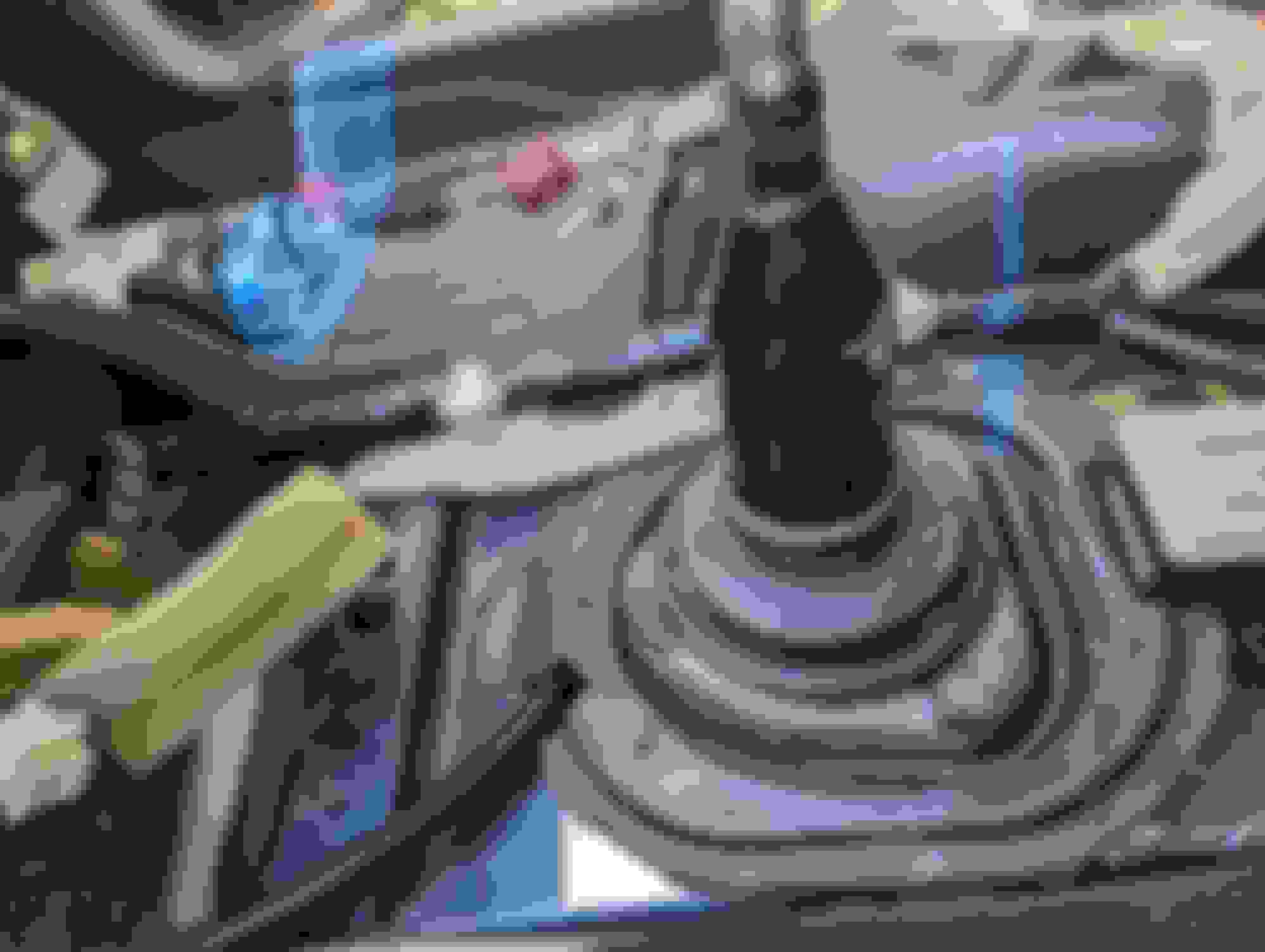
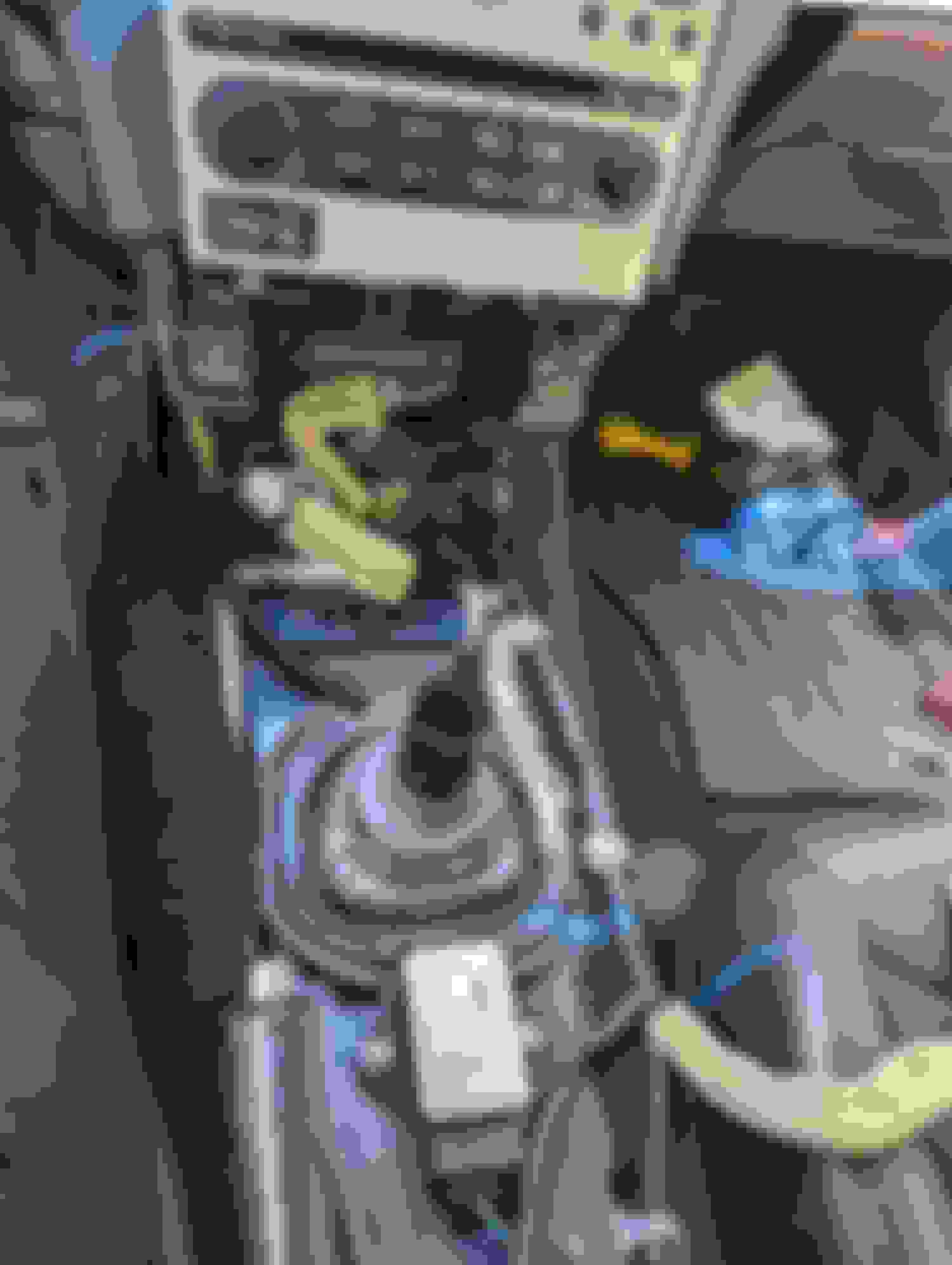
Removing the Auto Shifter
This one is very simple. From under the vehicle, there is a 12mm nut that can be removed freeing up the shifter linkage from the actual shifter. Up top there is one plug to disconnect, three places to remove the harness from and four 10mm bolts to zip out. With these removed, the shifter is now ready for its new home…In the BIN! Remove the Pin & nut from linkage Unclip this & This 4 Bolts to go and bob's your uncle.
Last edited by BxG3?; 09-01-2023 at 11:56 PM.
Reason: Part 2 Continuation
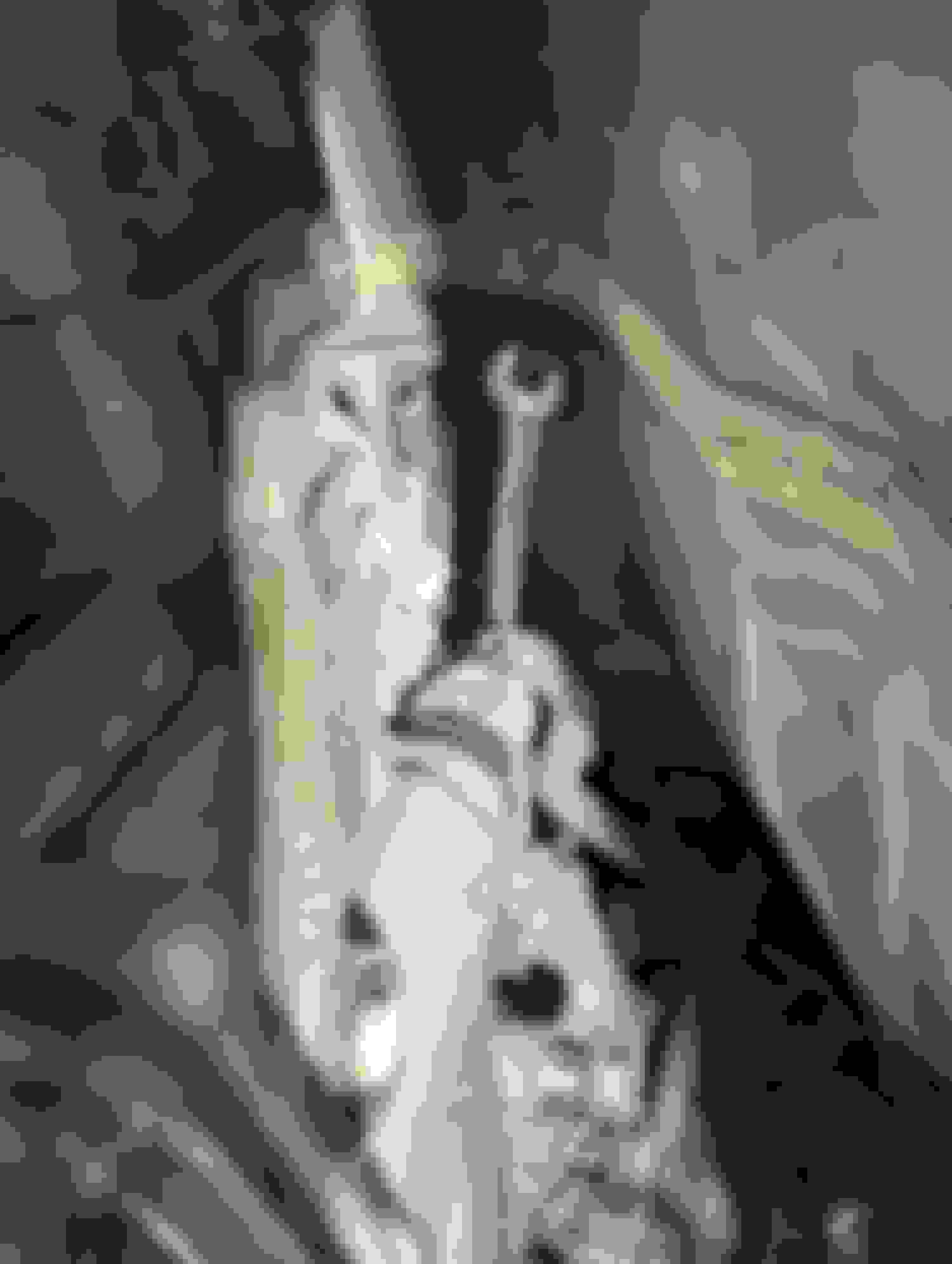
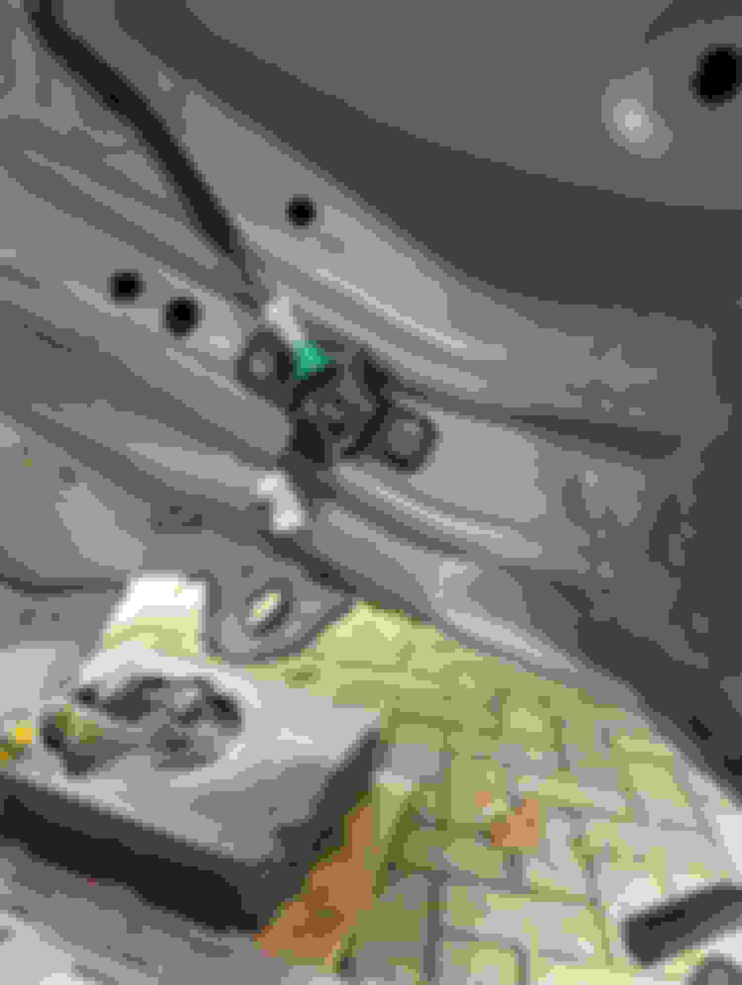
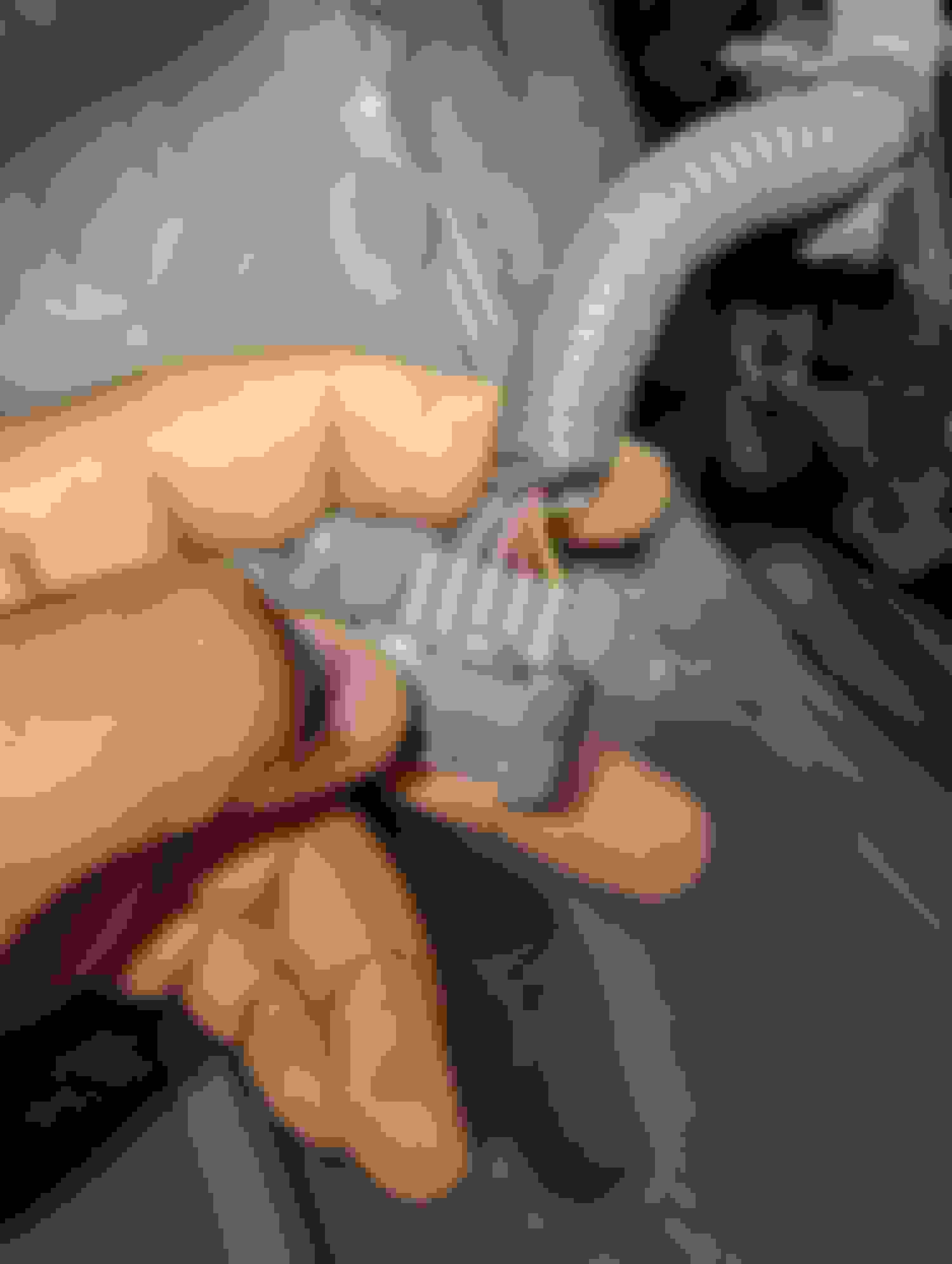
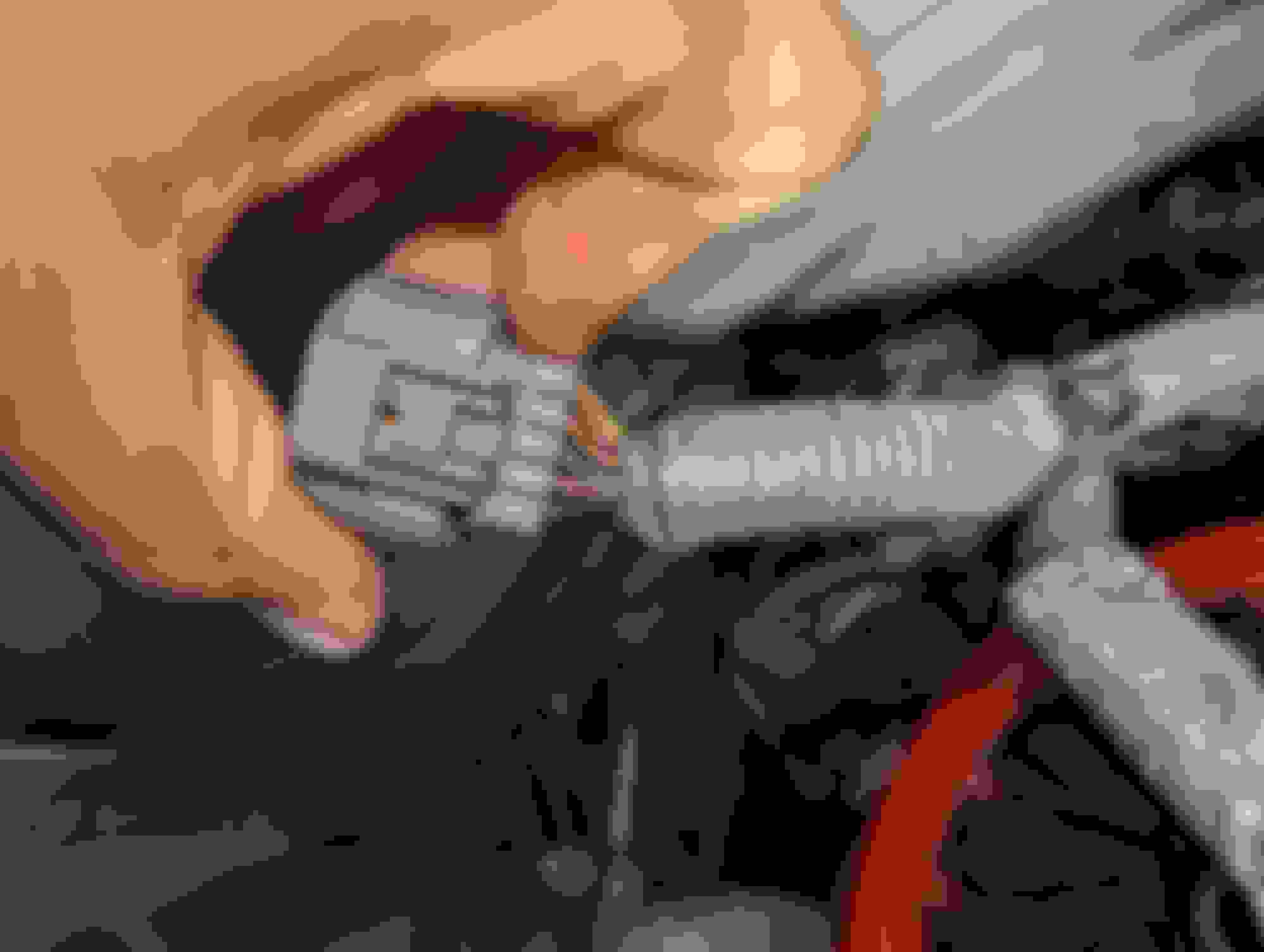
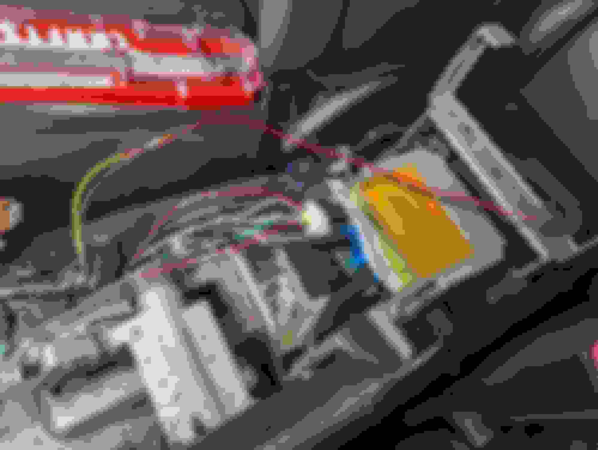
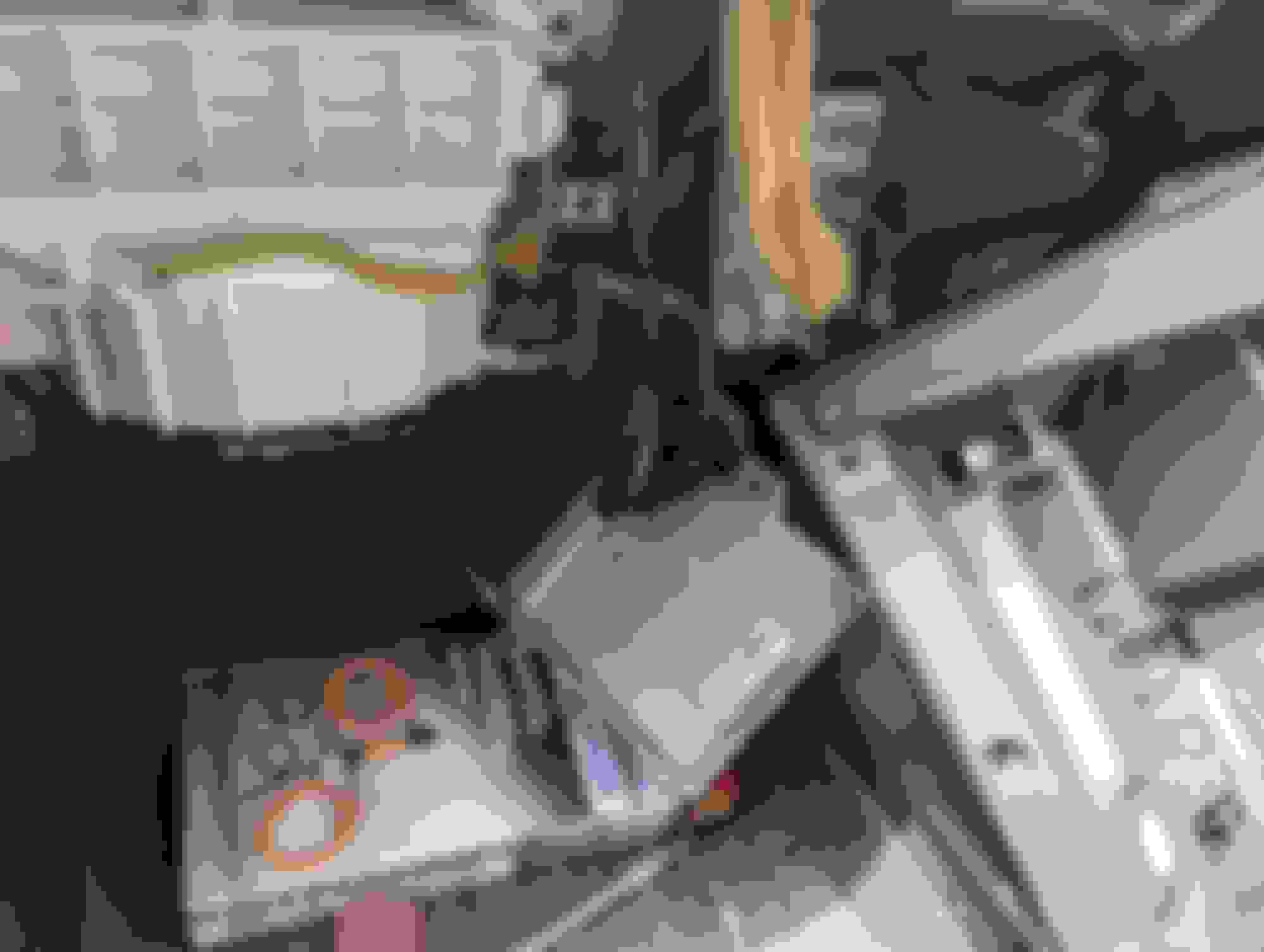
This needs to be done before you can drop the transmission. This one was a little messy but easy to keep clean with the right precautions. Use 12mm to remove the two banjo bolts that hold the lines on the transmission. I kept some rags around the area as well as have a drain pan ready to collect the fluid. There are three clips with a small 8mm nut holding both lines in place. Use a small 1/4in drive and a small ratchet to reach them. The one closest to the driver side wheel might be a little tricky, but it is easy to approach it from the front of the engine and not from the side.
From this point you need to disconnect the hard line from the rubber lines. I used a two way pump to help flush out the remaining oil in the lines from both sides. Once that is done, you can remove the rubber lines from the radiator and you can cap them with rubber caps. Now you can remove the hard lines. Be careful as there is the power steering rack around it. For me the easiest way was to pull one of the lines as far forward as possible so that is popped out of that recess and then you can remove the other line easy. I did try to cut it to make it easier but I was able to bend the a little to help ease it out. There is limited room to cut if you choose to do so but have some patience, play with it and it will come out (eventually). Easiest tab to get to. Most difficult tab to get to but approach it from the front just like the pic. Pull these out. Use a pump to remove all the remaining fluid. Bottom most trans line hose. Plug the top. Plug the bottom. Its tricky but able to be done from this angle. Using the access port, manipulate both lines so that you can go ahead and pull the lines out from the front of the car. Patience is key.
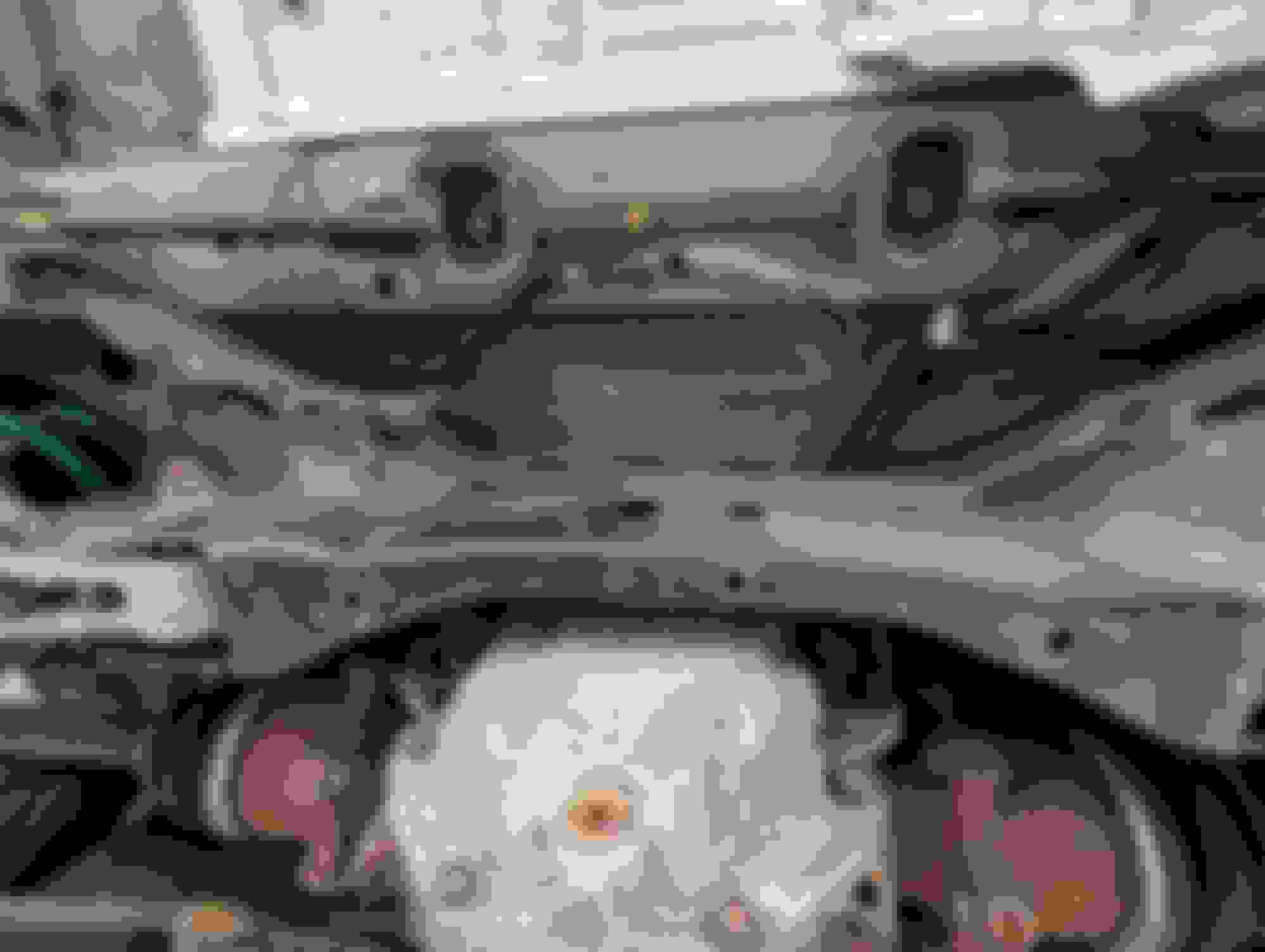
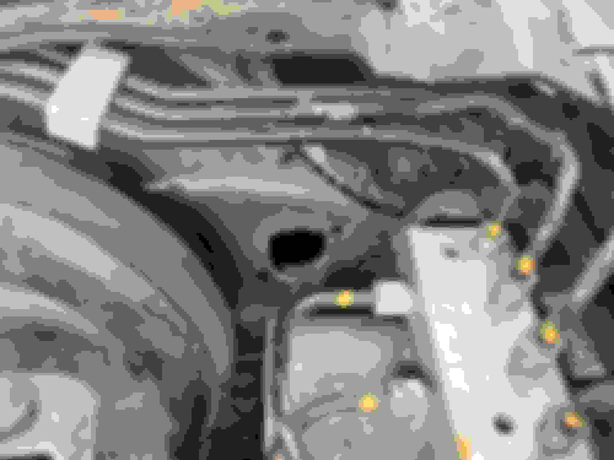
Removing the Starter, Transmission & Torque Converter
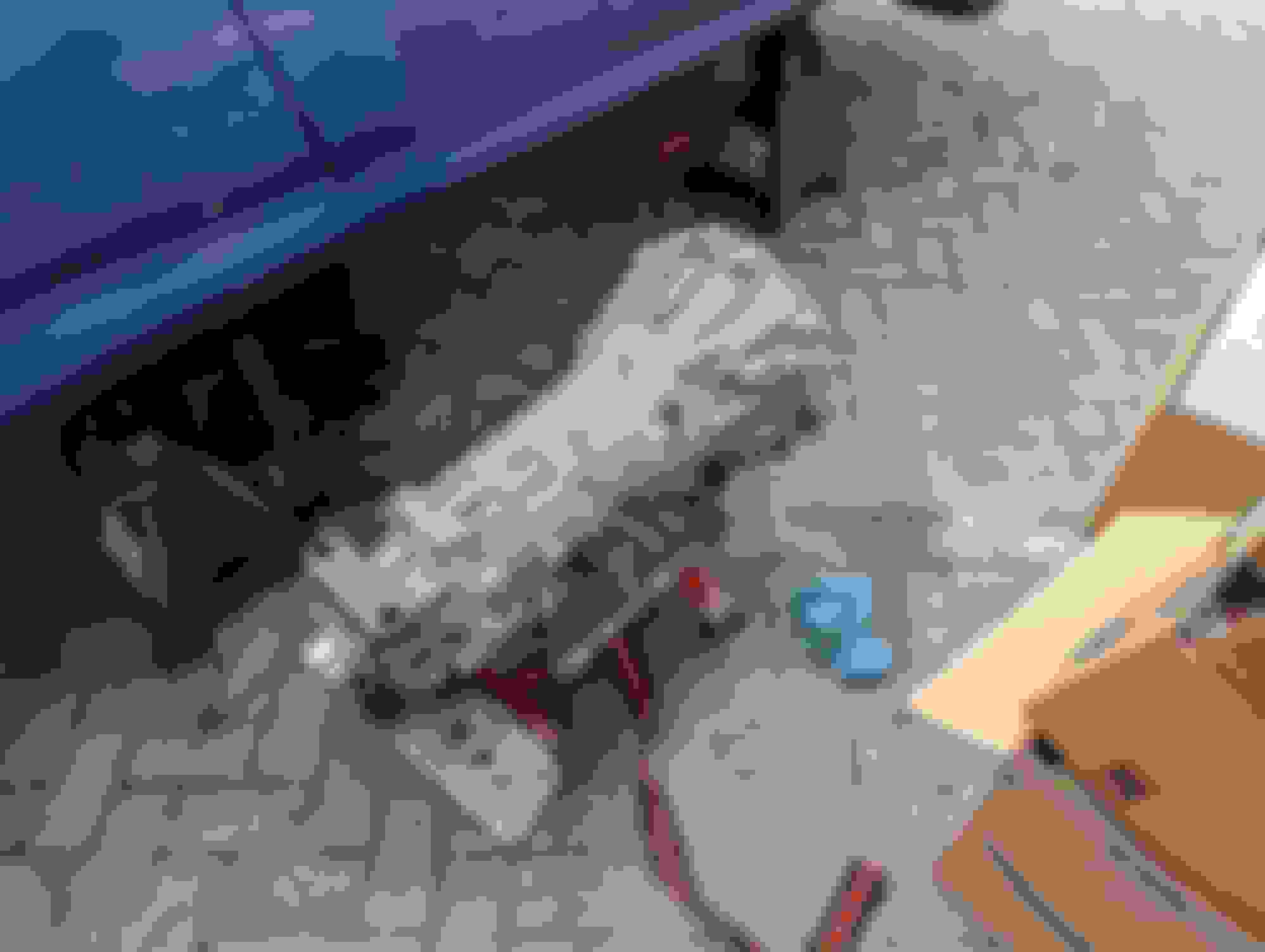
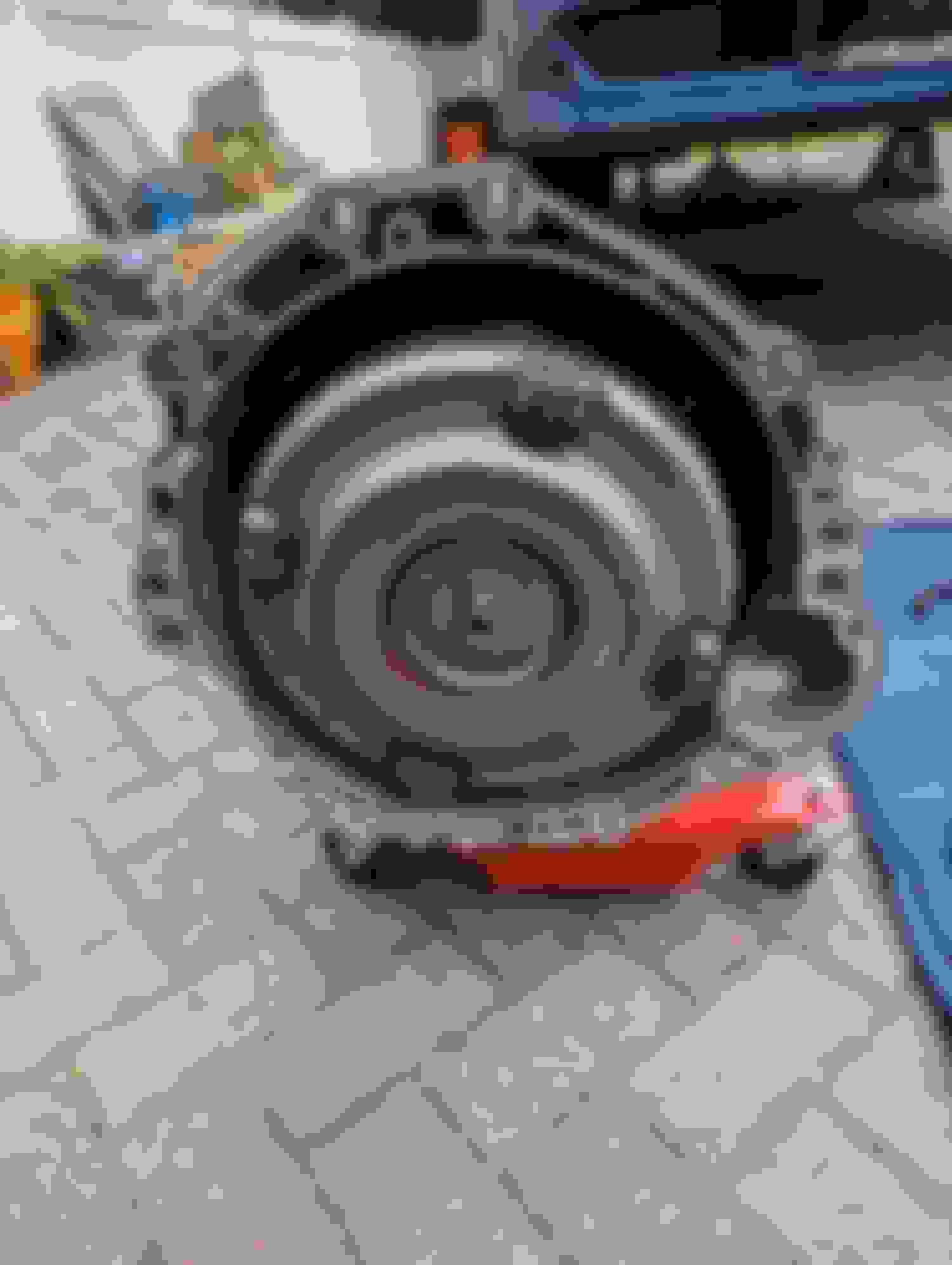
This felt like it took an eternity to get to but honestly took about 15 minutes once everything is off and disconnected. Before you begin make sure to drain the transmission to help decrease the weight and make it easier and safer to remove. There are four 14mm bolts to remove from the back side of the transmission, eight 17mm bolts from the front side of the engine. And two 14mm bolts holding the starter in place. There is a plate under front sub-frame to remove along with the service panel. You can remove the service panel by removing the two push clips and the two 10mm bolts. The rest of the plate are four 14mm nuts and two 17mm nuts. With all those things removed you can begin to loosen the four 14mm bolts for the transmission. There is also a small metal plate with a single 10mm bolt to remove which gives you access to the torque converter. There are four 14mm bolts holding them in. I had a flex head ratchet wrench which helped in removing these bolts.
By doing this, you can remove the torque converter along with the transmission in one go. You can use the shifter link on the transmission by putting it in N and then in P to help move the torque converter along to aid in removing the bolts. (The positions are the same as it would be on the AT shifter. Just listen to the clicks). Once completed, you can focus on removing the starter. Make sure to disconnect the plug before moving it. I found it easy to put my hand in from behind (facing the front of the trans) and pull it back and rest it softly on top of the steering rack to help make room. From here you can focus on removing the other bolts. An assortment of extensions, and swivel connectors will help you get to the upper most bolts. I used a � sockets and extensions for this, but you can use 3/8 if you have no available.
There are some brackets (10mm bolts) as well as the breather tube towards the top of the transmission. They hold in the harness which you can disconnect the tcm and when the brackets are unbolted you can move that to the side. You have to also unbolt the two 14mm bolts holding in the O2 sensor bracket as well as the four 14mm bolts holding the brace. Use a flat piece of cardboard to help keep the transmission bolts in order so that putting them back in the right orientation when the time comes. Once all bolts are removed, all harnesses and brackets are out of the way, use a transmission jack to support the transmission. You can now go ahead and undo the four 14mm bolts holding the trans crossmember. You will notice that the trans will slowly dip downward from its weight. From here, just wiggle it and pull back slowly. There are two dowel pins that keep the trans aligned so you need to get past that before you see any real movement. You can slowly lower it adjusting as you go and then it should just plop out. Hopefully your car is high enough off the ground so that it can be removed with the trans jack. If not, you can pull it off the jack and drag it out from under the car. (This is what happened to me as it wasn�t high enough on 12-ton stands.)
Pull the starter back approaching from this angle once unbolted. Remove the access port. Spin the flywheel to remove the 4 bolts from the TC Remove the tube. 2 on trans, 1 halfway up, and the top 1 behind the motor. Remove the breather hose and harness bracket Said bracket Another Bracket to undo. It its too tall on the jack, throw it on the floor and use brute force to remove it. Go Muscles! Torque converter out attached to trans. (May have fluid if you didnt drain it properly.)
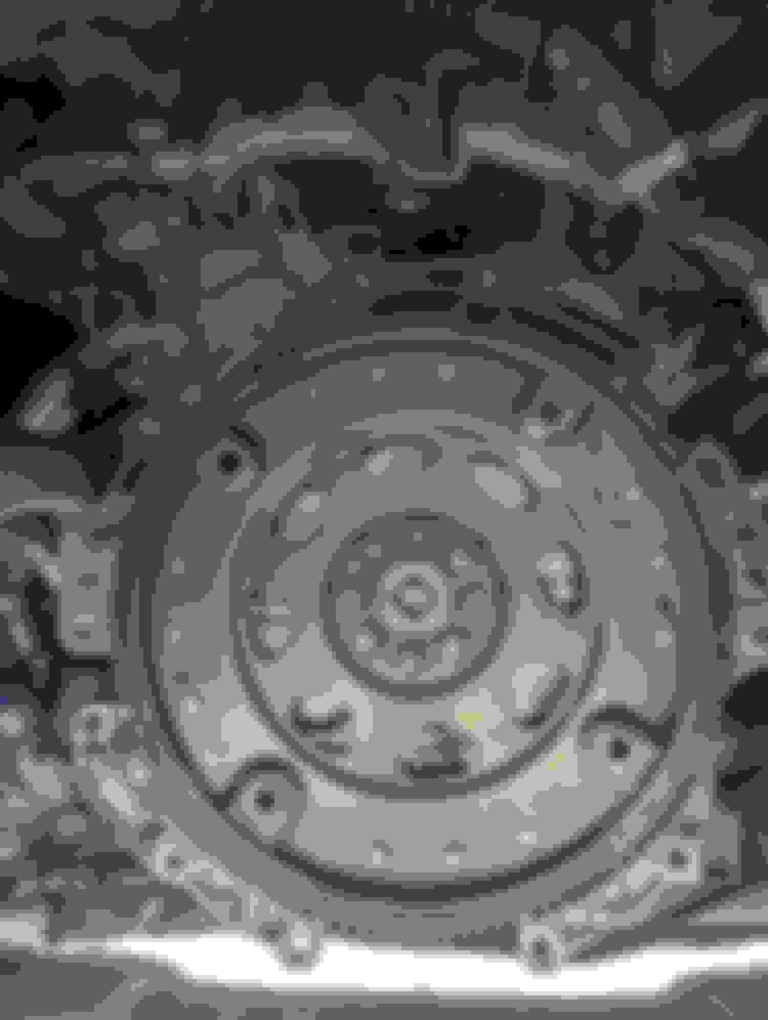
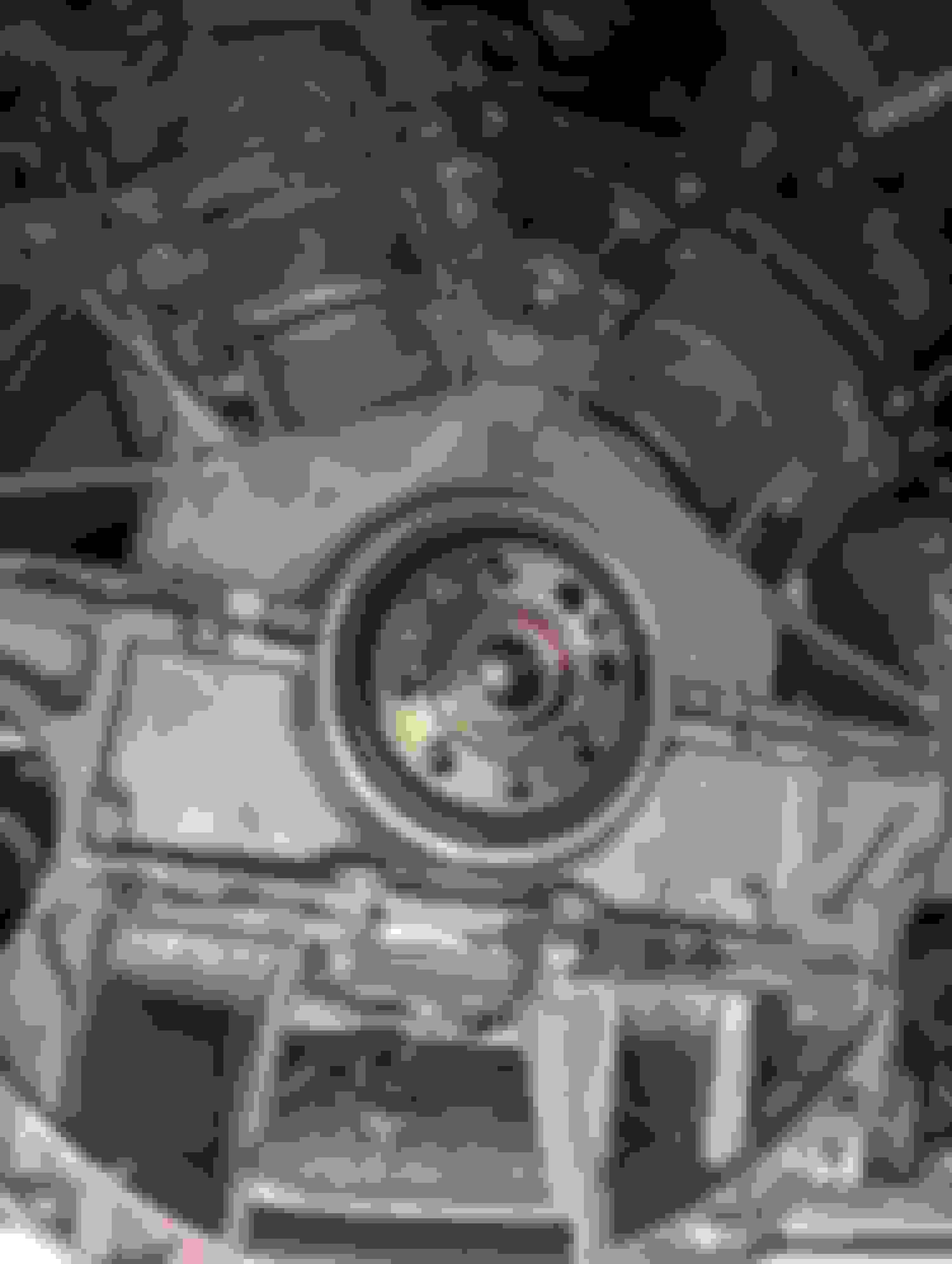
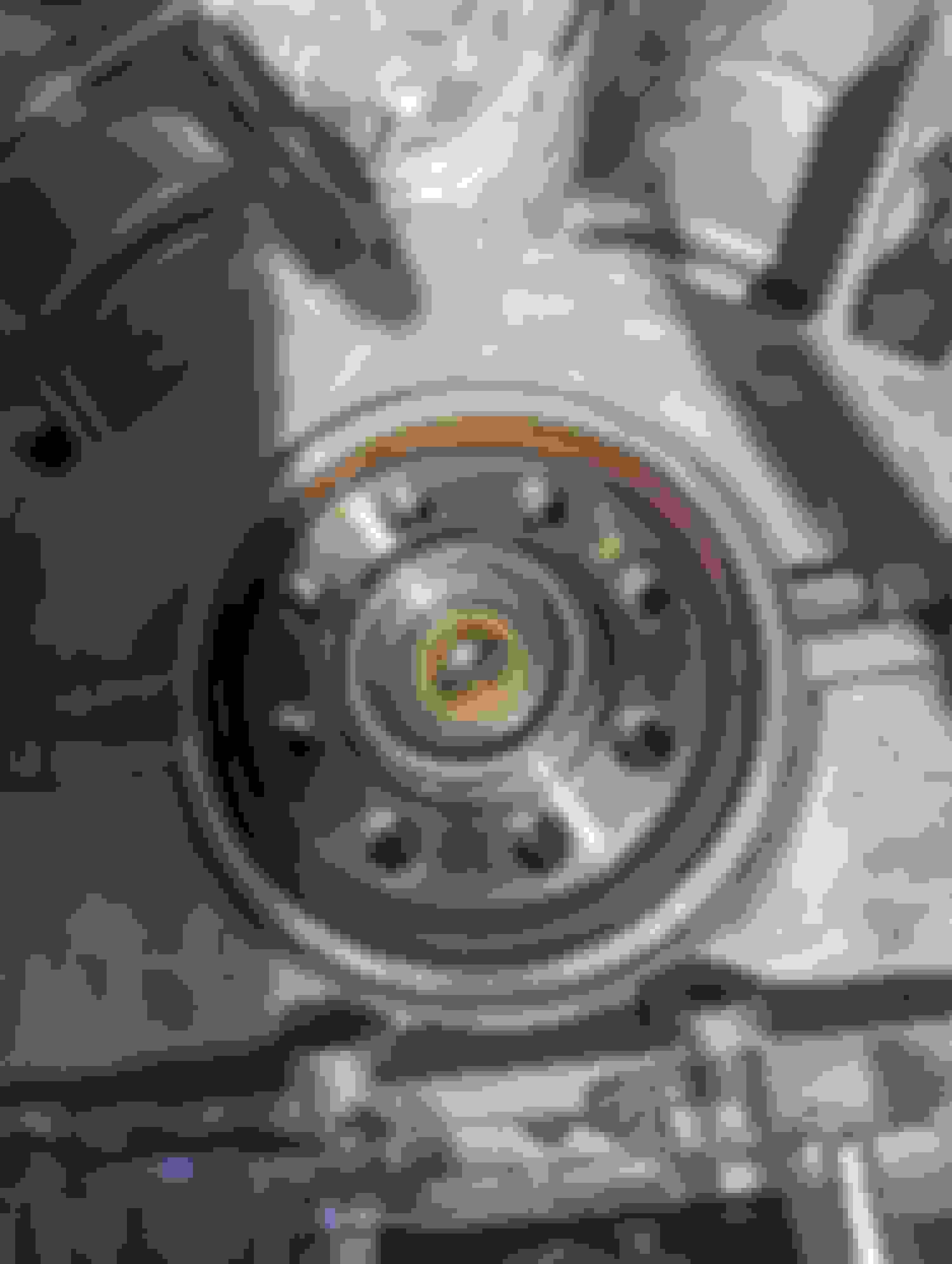
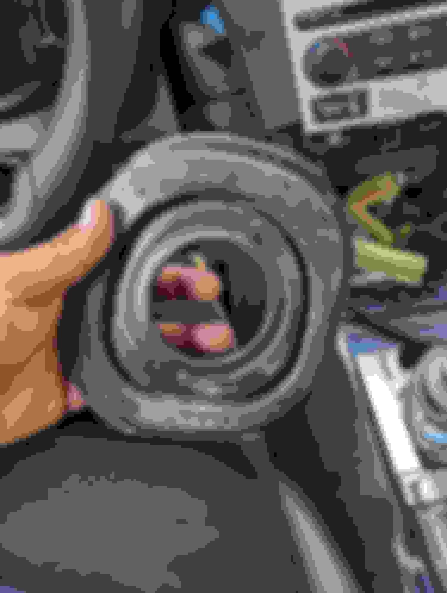
Removing the Pilot Bushing & Flex Plate
The final piece of the puzzle for removing the remnants of the AT. Eight 14mm flex plate bolts need to be removed. You can use a long screwdriver or have someone hold the crank in place with a long bar and a 19mm socket so that the flex plate doesn�t spin when you go to loosen it. You cannot use these bolts with the flywheel as they are too short and do not have enough thread to hold the new flywheel in. The flex plate may be stuck but it will come off with some gentle persuasion. Be careful as there is another smaller ring plate that may fall out once the flex plate begins to loosen. The flex plate has some weight to it so be careful not to drop it on yourself. With that out of the way the pilot bushing is in full view.
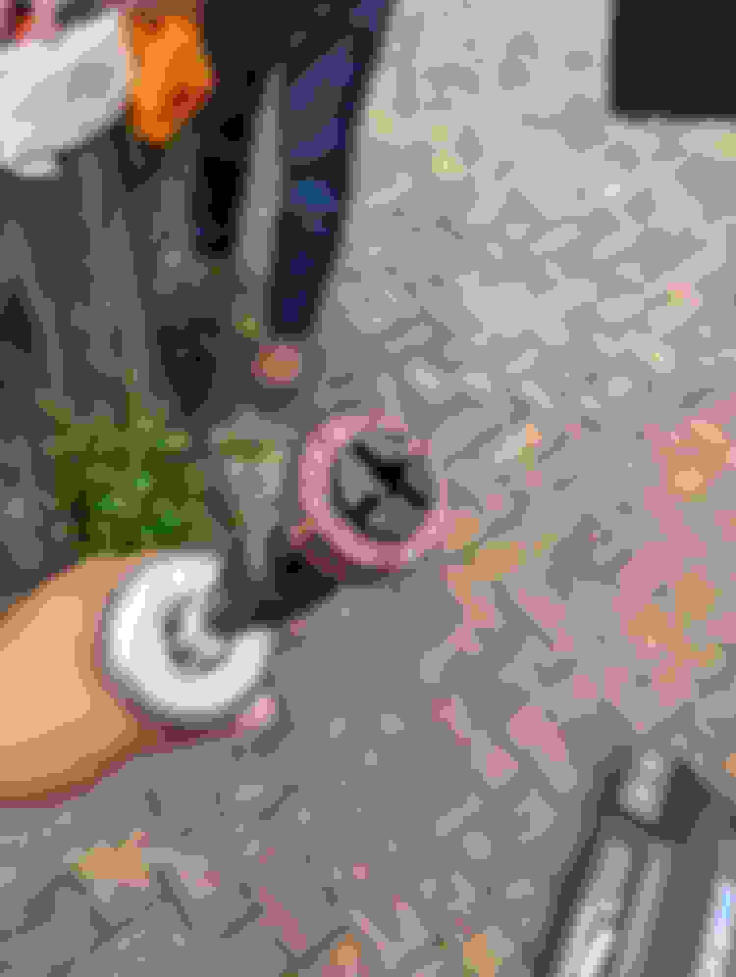
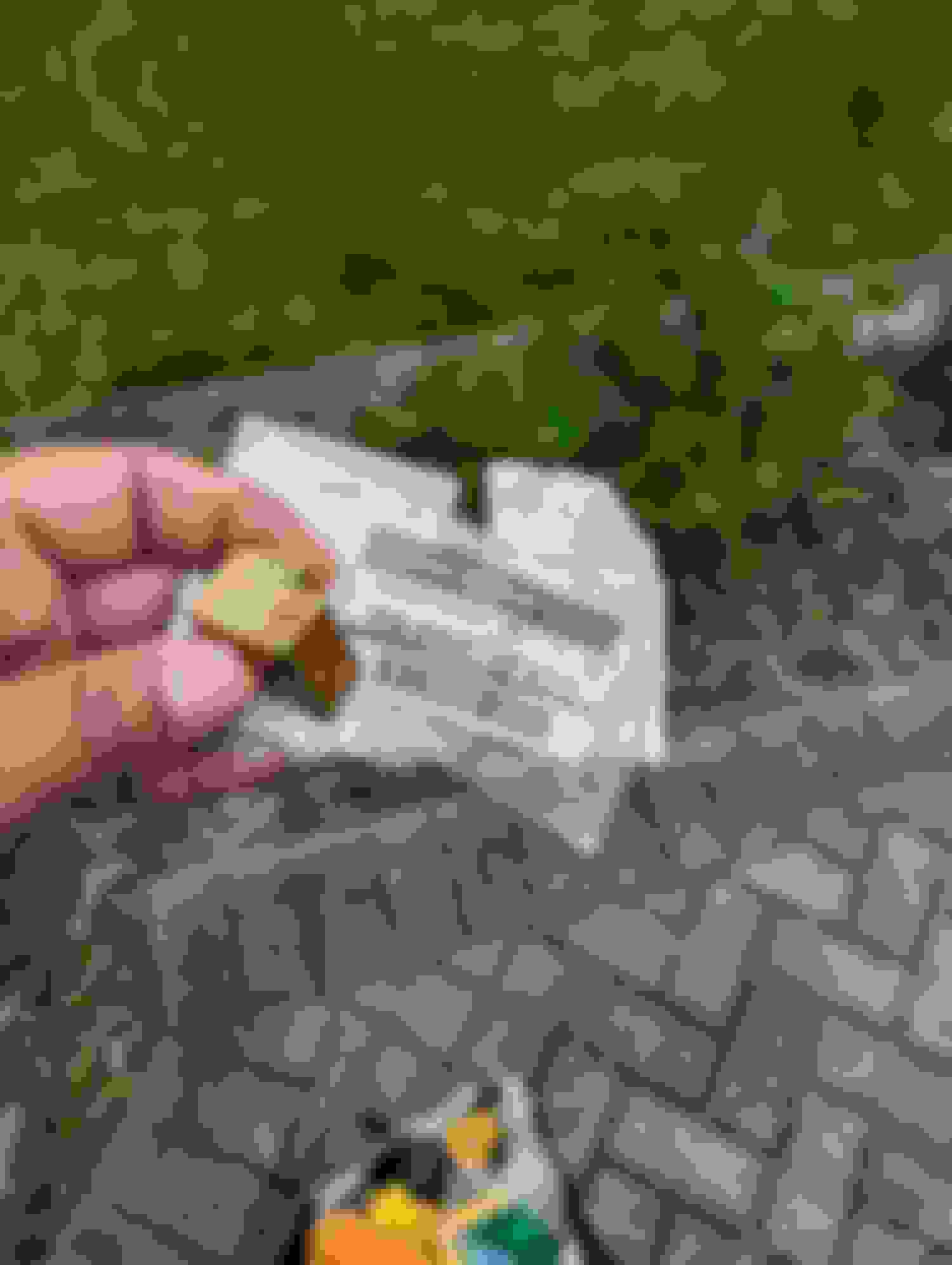
There are a lot of way to do this. I used a two-tooth puller, and it did not work with the 4lb slide hammer. I ended up breaking the tooth on the puller. I tried the rod/bolt and screwdriver trick, and it did not work. I tried packing grease & hammering away but it did not work. It did however, help lube up the space between the bushing. What did work was using a four-tooth puller and upping the weight on the slide hammer from the dinky 2lber to a nice beefy 4lber. I got the four-tooth puller from HF and after 10 minutes of using all my strength to slam the bejesus out of the slide hammer, it finally popped out. I found out later that it was a steel bushing and its now a nice paperweight on my desk as a friendly reminder. Time for you to go! This puller wont work. Its out but how? 4 point puller with a 4 lb hammer & Grape Jam
Mounting the clutch pedal assembly & Master cylinder
Now that everything is removed, this is where things become a little more complicated. The best-case scenario is that you have a cutout on the padding that should show you exactly where to mount your pedal. I ended up using the rubber gasket from the master cylinder and used it as a template to mark my points inside that cutout area. It can only fit one way so that makes it easier. For those without the cutout in the padding, you will need to line up the back of the pedal assembly with the back of the firewall and find a way to mark the hole locations. Perhaps a paint pen might do the trick if this is your situation. If done properly you will notice that the clutch spring is close to the side panel that covers the fuse box in the foot well. Also, you will notice that the pedal is roughly in line with the brake pedal. You can then mark your area with the rubber gasket, open the hood and remove the plastics over the brake reservoir and then you can use a step bit or drill bit to make the holes from the foot well. (When mine was done I didn�t realize at the time that I was over to the left by about a � inch.
I used a step-bit and then deburred the edges. Take your time on this part as there is not a lot of metal to spare if you cut too much. I frequently checked as I cut to make sure I didn�t bump into any harnesses or the brake booster. My mistake when I did this was that I did not accommodate for the rubber boot on the other side of the firewall. (I should have moved my cuts down and over about � inch to have the master cylinder fit flush against the firewall. Instead, I used my deburring tool and trimmed the lower metal edge of the master cylinder to make sure it fit flush against the firewall and that it cleared the rubber boot.)
The bracket holding the old foot e-brake is in the way and you need to trim/cut it off to fit pedal flush against the firewall. This is one of the hardest and most time-consuming part of this project. Either a Dremel 4000 or die grinder will do the trick. I was worried about sparks and metal shaving catching the insulation on fire. I did see some smoke in a few places but nothing serious. I used aluminum foil to wrap around the areas to avoid any mishaps. I also advise taking your absolute time as it is a very tight space & trimming the upper bracket is the most difficult. (Initially I noticed that there are spot welds, and tried to drill it out. If you go this route, you will be drilling up into the cavity where the wiper motor lives. Shortly after starting this I noticed that it was going to be a pain to pull off the bracket without a chisel/pry bar and not warp the metal in the process.) Using a Dremel with a 1.5 in cut off wheel, I set the speed to 30k and made many cuts. I used a very robust but small profile needle nose pliers to help roll back sections of the bracket to let the Dremel go to work. The best reference point for this is by txboostlife on YouTube where he did a 6mt swap on a q50. His bracket was cut differently than mine, but the results were the same. I cannot stress again to take your time. There are a lot of wires in the vicinity, and it would suck if you nicked a harness.
With the bracket gone and the hole cut out, I used a small flap wheel on the Dremel to clean up any edges. Then I cleaned the area and hit it with some Rustoleum paint n primer to help prevent any rusting. If I had planned ahead I would have gotten a paint match can instead.
From here you need to grind down the bottom & then it�s time to secure the pedal in place. Make sure the master cylinder sits nicely up against the firewall and isn�t snagged on anything. Test fit a few times to get it right. Make sure you put the rubber gasket in place before putting the master cylinder on. It would be beneficial to have a friend help you. It may look tight, but you do not need to remove the ABS pump. It might make things easier but, you can slip it through the hole and have it fall into place nicely. Don�t force it! If you have any resistance, back out and trim the area a little more if needed. Once in you can mark your third point to help secure the pedal which is advised because over time if you don�t use the top mount the firewall will begin to flex and may crack.
When you look inside the footwell up towards the firewall you will see a marking which indicates that there is a third mounting point for the pedal. In manual cars they have a tab that is welded on with a bolt and you secure the top of the pedal via nut. You can make a bracket and secure it as it�s a tight space (1.5inches roughly) or you can use a rivnut/nutsert. I went with the rivnut and was happy that I went that route. You need to get a long drill bit and drill a hole where the marking is for the mounting point. Then just install the insert and then secure the pedal in place using a long M6 bolt w/washer and some blue Loctite. You will know when you are done when the bolt starts getting harder to turn. The pedal will feel much more secured than it will with only the 2 points at the master cylinder. Find the cutout! Use MC grommet as a guide. Moment of no return. Looks good inside but check up top first. Fits but I did not notice the MC was on top of the harness boot. I needed to move the MC over by .25 inch. Widening holes for ease of install. Dont cut too much metal is thin. Final product. Trimmed MC to fit flush on firewall. Fits Nice! Time to remove this bracket holding the e brake. Patience is key. Those 2 divots are where I assume the the tab would be welded on for the third point of the clutch pedal. Drill a hole in the furthest one & put in a nutsert. Install the MC reservoir 7 check fit. How it should Look.
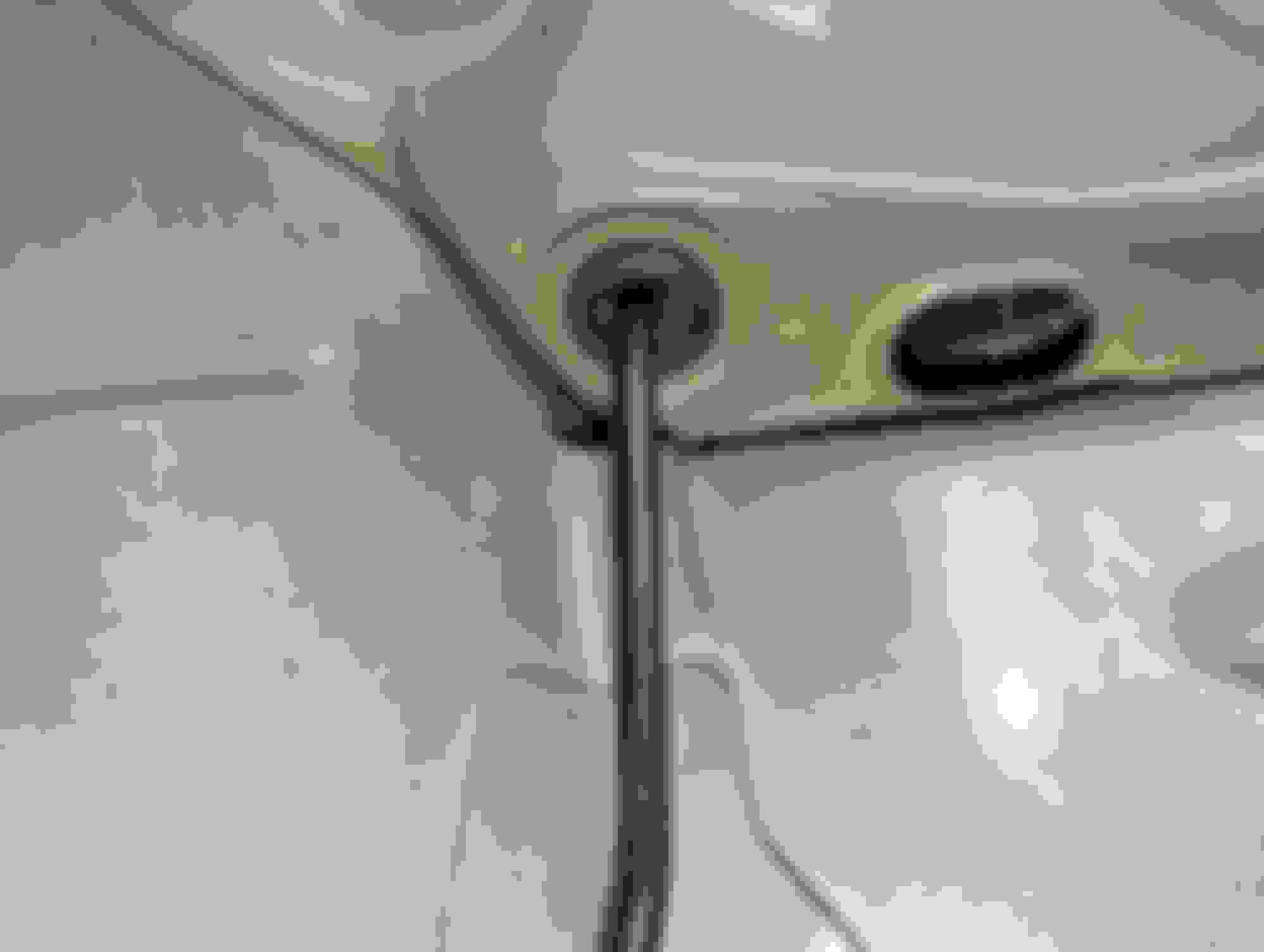
With the master cylinder in place it is time to mount the clutch line. You will notice a small rubber grommet under the brake booster. It is next to a larger oblong opening. You can remove the grommet from outside of the car in the wheel well (Remove the shield if you have not already done so.) You do not need to remove the booster to get this to fit. Going from underneath the grommet location, it is possible to snake the line up through and in towards the master cylinder. You may need to lightly rotate and angle the line but it is much easier than trying to approach it from the top of area. You may need to remove the reservoir and line from the master cylinder to give you some more space to help snake the upper line into place. Once in place, you can secure the line with a 10mm flare nut wrench. I used some blue Loctite as an insurance policy as I was unable to find any torque specs. This line comes with a grommet so you can slide it into place and use a small flathead to help set it in place from the wheel well. Remove that lower grommet. Access from wheel well. Insert the line from below and snake up towards MC. Make sure to check from up top. How it should look. Needed to get this bracket that holds the union flange. Found said flange from a used G. Ordered a new flange. Oh look, a part number!
Installing the Lower Clutch Line & the Flex Line
The same thing goes with the lower line as with the upper as it can only go on in one way and it already comes with both brackets. A brass union joint is required from this point to attach both hard lines. (A M6 x1.0 bolt works here if you don�t have the bolt to secure the union joint.) Just attach one side to the brass union joint and use the flare wrench to attach it. Then line up the other end with the little factory tab that is used to attach it to the rest of the clutch line that goes to the transmission. Once the that is lined up, make sure to pop in clips that secure the lower line to both sides of the wheel well. You can now attach the flex line that goes to the transmission. Since I did the csc delete kit from z1 my line attaches differently to the trans, but it is the same when attaching to the lower line. Make sure you line it up properly in that tab. Some people remove their cats/test pipes to get more room, but I was able to get a small crescent wrench and the flare wrench to make sure it was securely fastened. When you�re done there is a metal clip that slides into the tab to help hold the line in place. Lower Line goes in only 1 orientation. make sure to attach the line first before popping in the clips. Attach it to the SS flex line. Found the clip but you could use the e brake clip from earlier to do this but it would need to be modified.
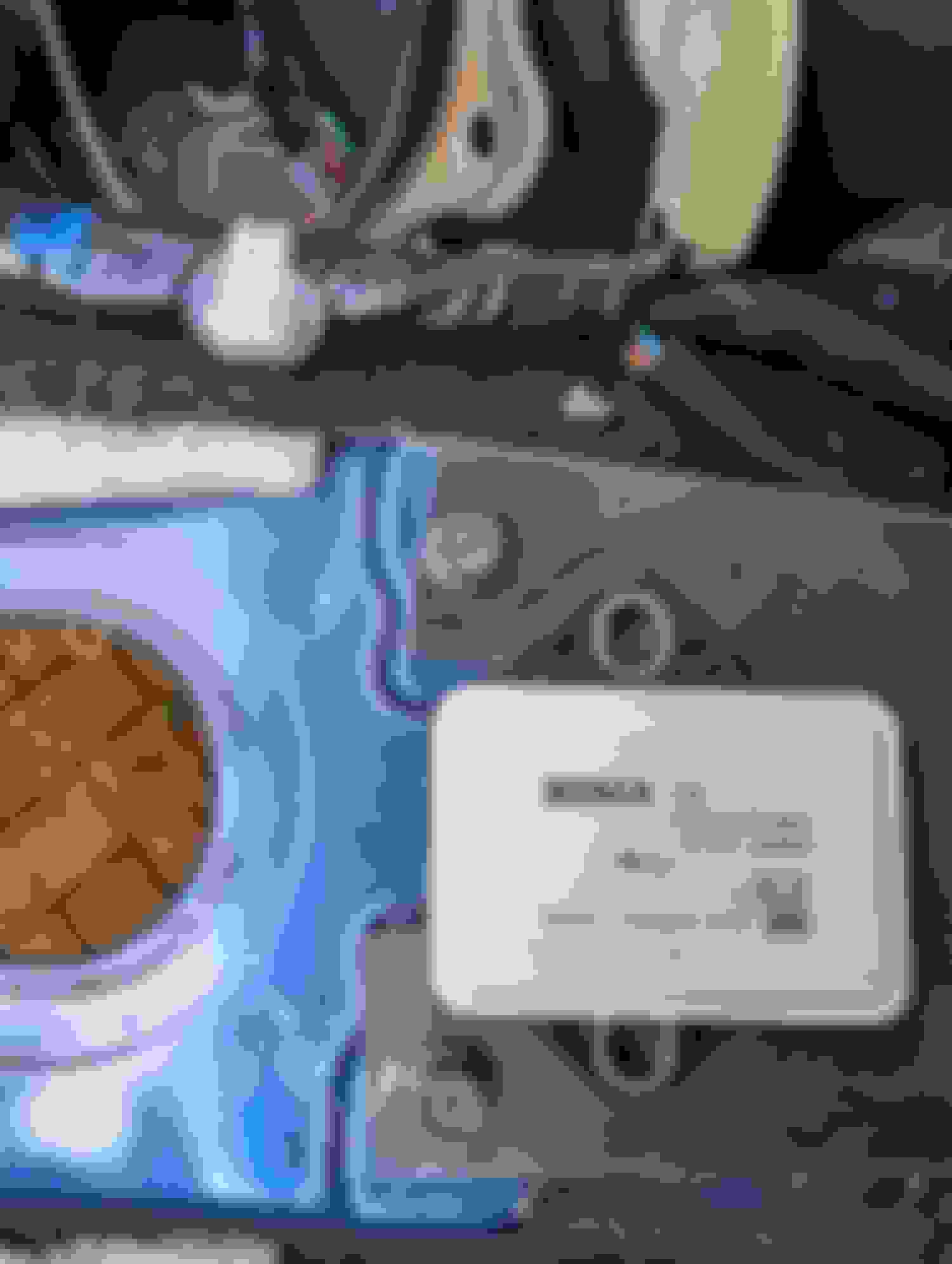
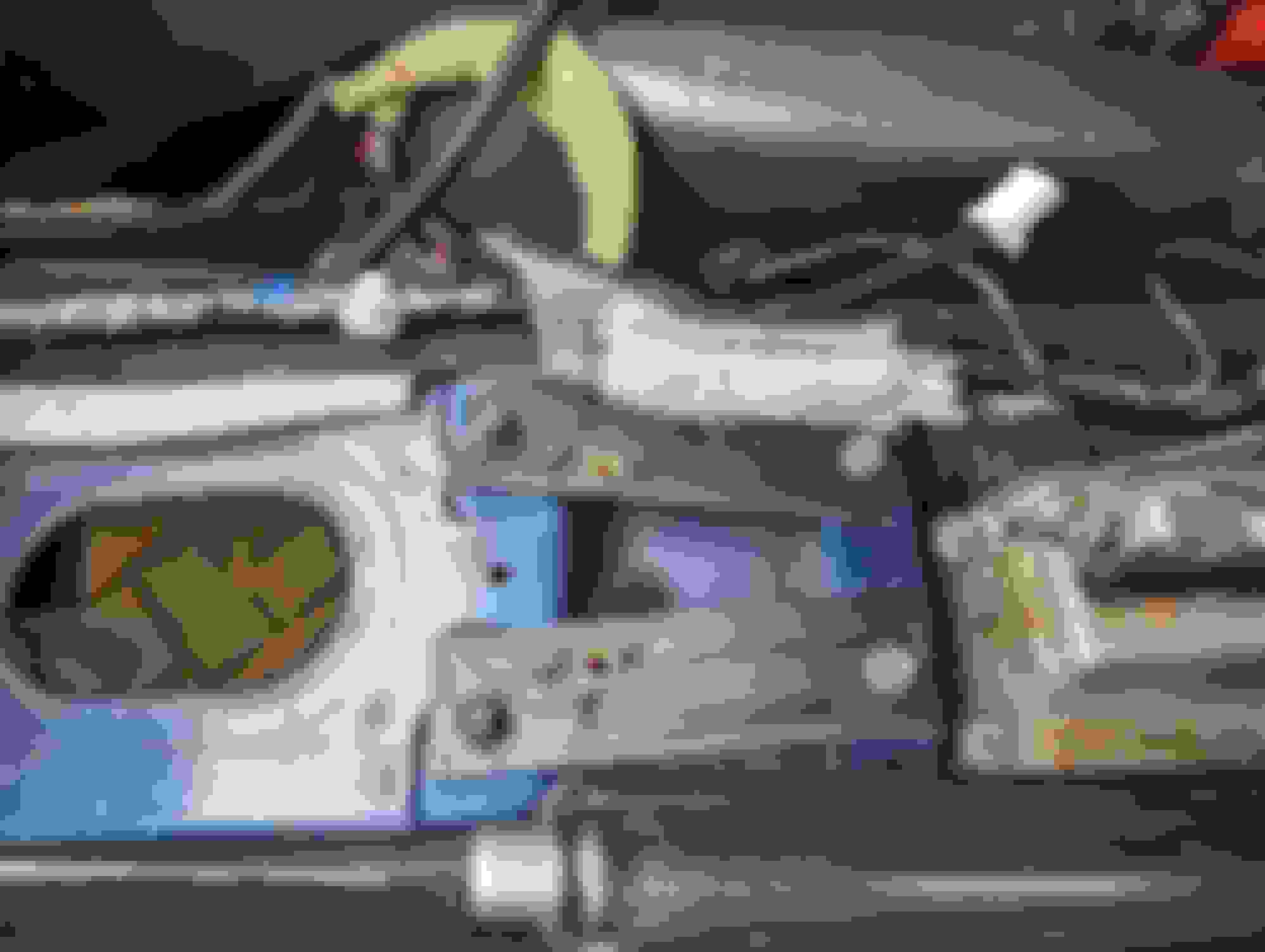
Installing Pinion Flange, New Bushings (optional) & the Diff
Installing new differential bushings are not necessary, but I figured why not since everything is already taken off (You can skip ahead past the bushing install if this does not apply to you). Most people just buy a used manual diff. In this case because a used one is pricey, I decided to just change the pinion flange. The 08 5spd auto came with a 3.69 diff but the pinion flange is the dreaded y flange and not the nice circular flange we all love. Other models of G�s and Z�s use the circular flange on the auto as well. A 30mm socket is needed to release the pinion flange. Before I removed the flange, I removed the nut and went ahead and cut down the rod right up to the threads that the nut was attached to & made it smooth. You need to cut this as the MT driveshaft won�t fit properly if left on. If doing this on the car you can use a pinion puller to remove the flange however, because mine was already out, the use of a slide hammer helped me remove it. (At this time, I was unaware of the pinion seals and that you should use new ones. Thankfully no leaks currently.)
Once it was out, I used a rubber mallet and a block of wood to drive the new one in. (Its moments like this that I wish I had a press.) Make sure you put it in properly so that it aligns well with the grooves before you begin to drive it in. (You should use a new nut) Once in you can thread on the nut. Torque specs are in the fsm, and it suggests you torque on the vehicle. I did use an Impact to secure the nut in place, but this is ill advised. I did not however go �full send� on the impact so maybe that saved me.
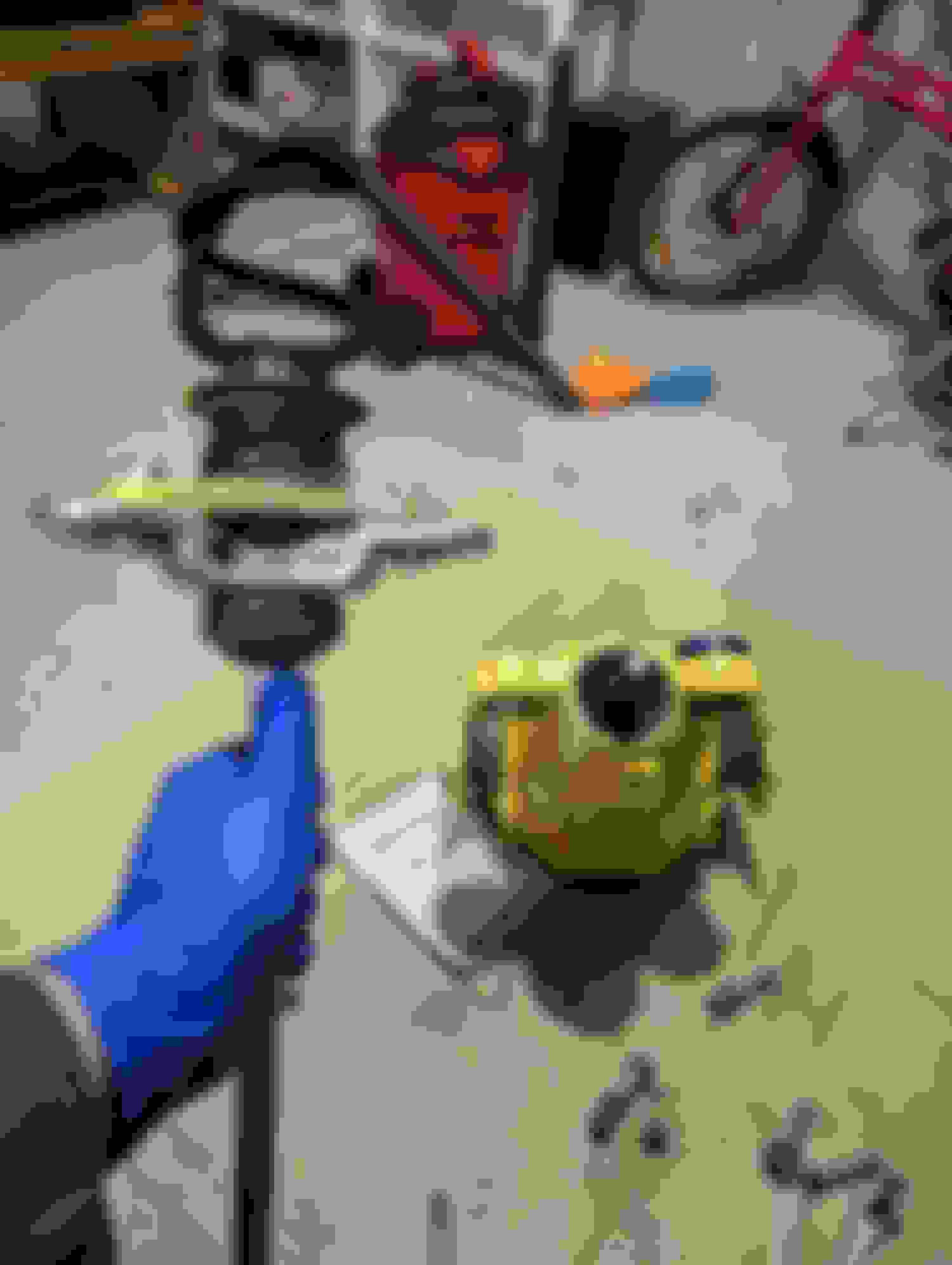
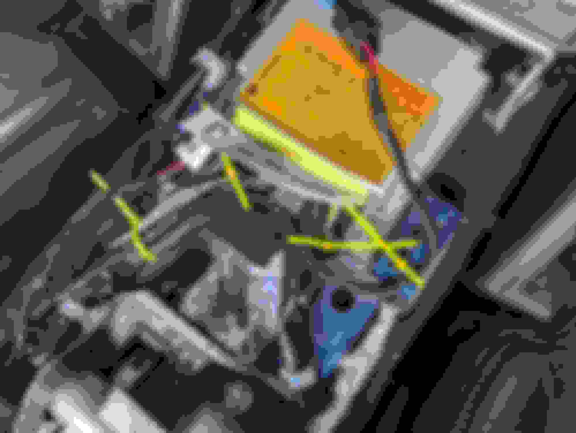
(Skip this if reusing OEM bushings) The bushings are a different beast altogether. Hardest part was the one on the subframe. I used the z1 bushing tool and it was easy to take out the core but living in the northeast it was extremely difficult to remove the outer sleeve. I used a Sawzall as well as a chisel and a 4lb sledge to get it out. Be careful not to scratch the inside and if you have any nicks, use a file to bring down any sharp points. Use some grease to help slide in the poly bushing and use a rubber mallet to help set it in place. Using a 32mm socket you can remove the 2 smaller bushings on the diff with a few well-placed blows. These bushing slide in a particular way as per the z1 instructions.
With all the new stuff in you can go ahead and re install the differential by reversing the process. Remember to put the breather hose back in and to reconnect the abs sensors. To finish this part, refill the diff with new fluid. You need to get a steel bar and create a tool to help torque down the nut on the pinion flange as per the fsm. I cut a notch in the bar & used some M8 bolts to help attach the bar to the flange. This will help to stop it from spinning when you go to torque the flange to spec. 34 MM to knock out the diff bushings. Tada! Z1 tool works great for the inner part. Not so much for the steel ring. Chisel, 4 lb Sledge, a Sawzall & 2 hrs later... Why not. Cut that rod to allow the socket to fit. Puller to remove old flange. Cut it down to the threads. If not DS wont fit. Thats nice! New flange on. Make sure its flush! Home Made tool to torque flange as per FSM attach it well. Tighten it as per fsm. Go Muscles!
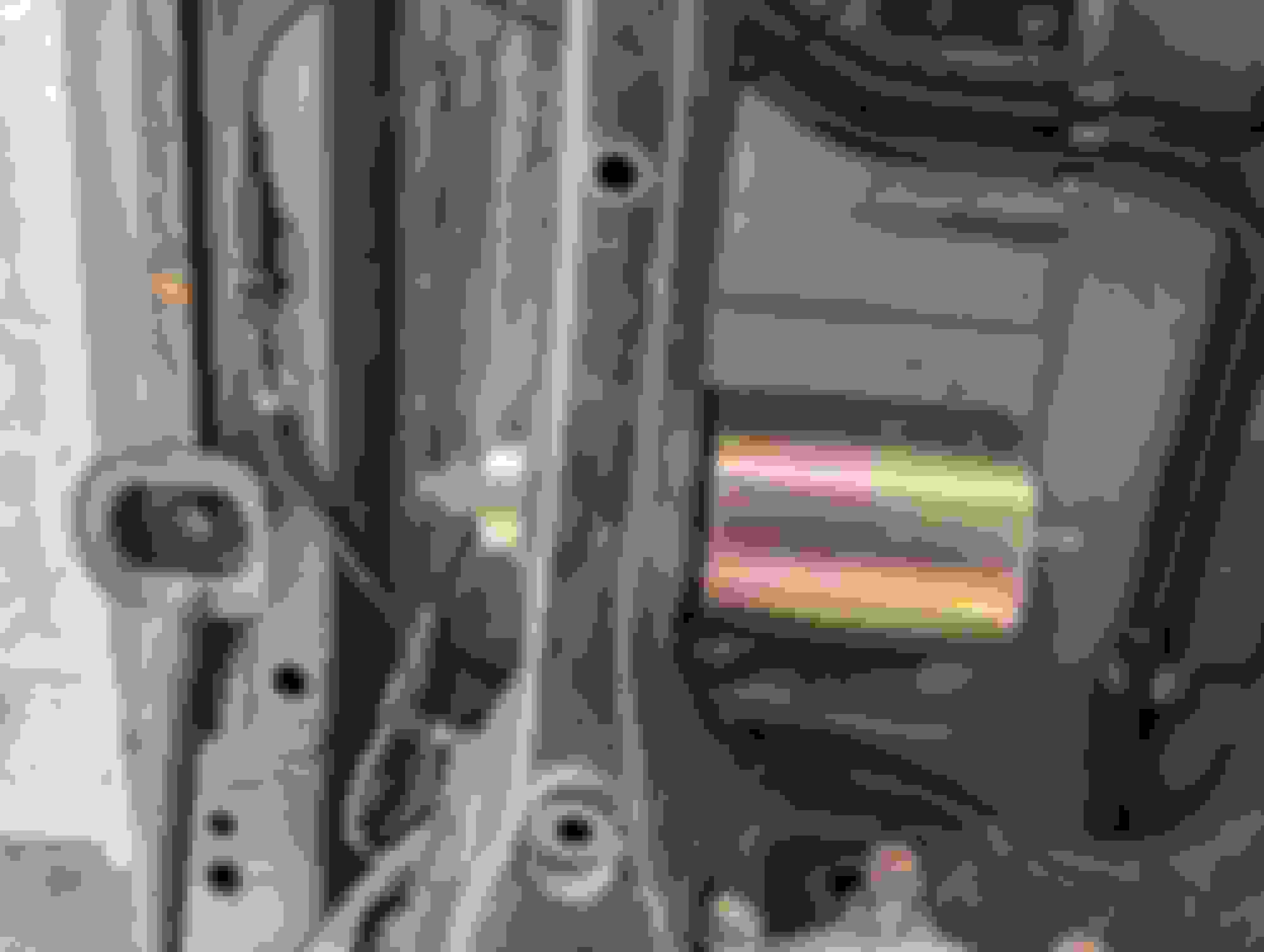
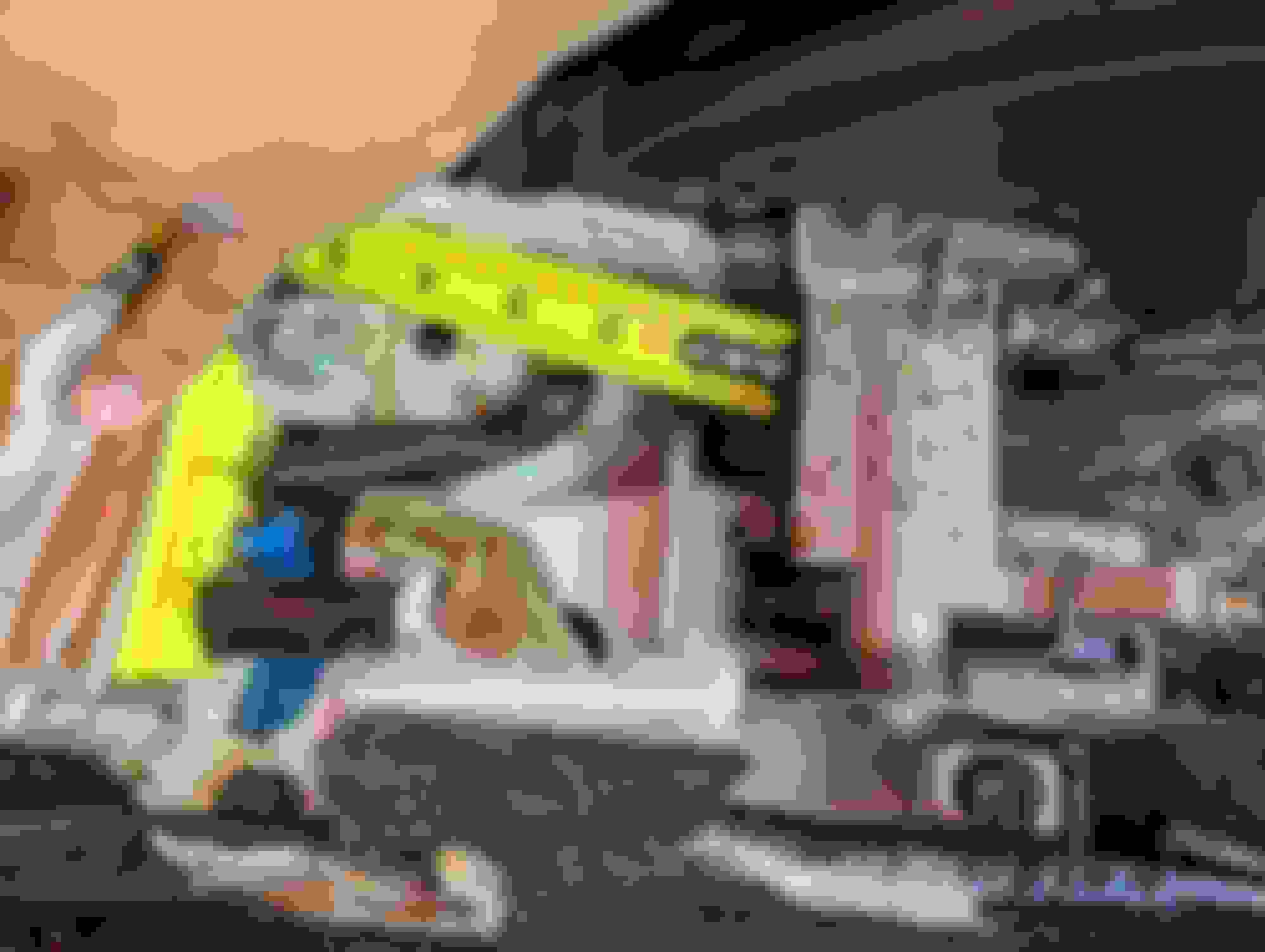
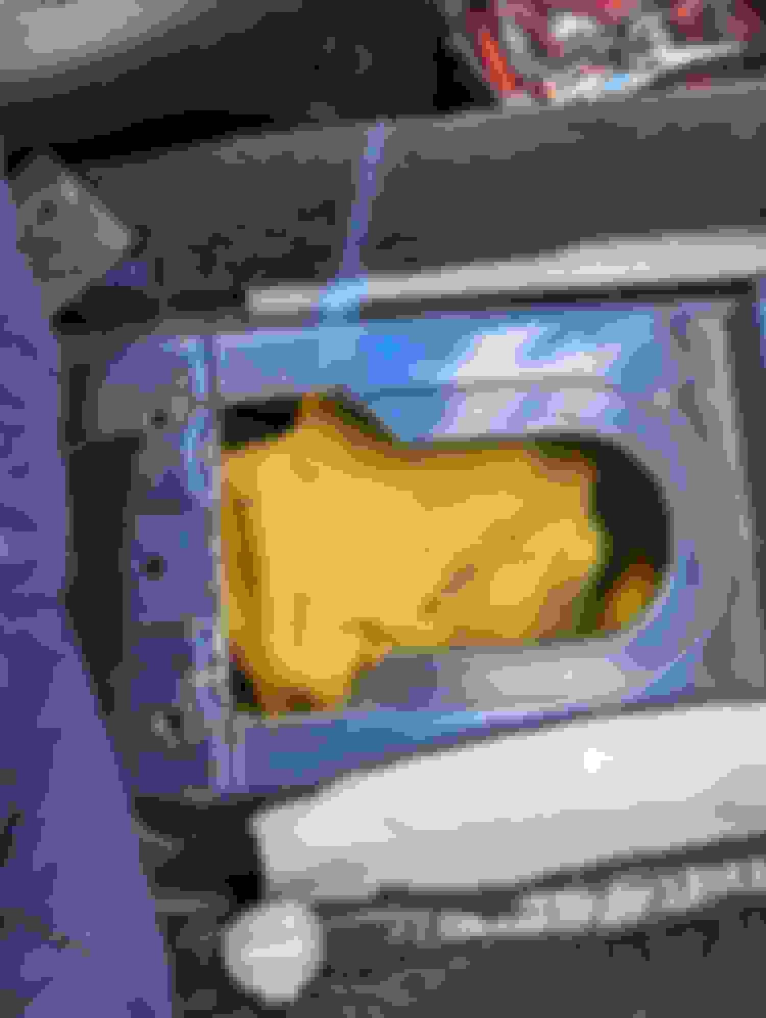
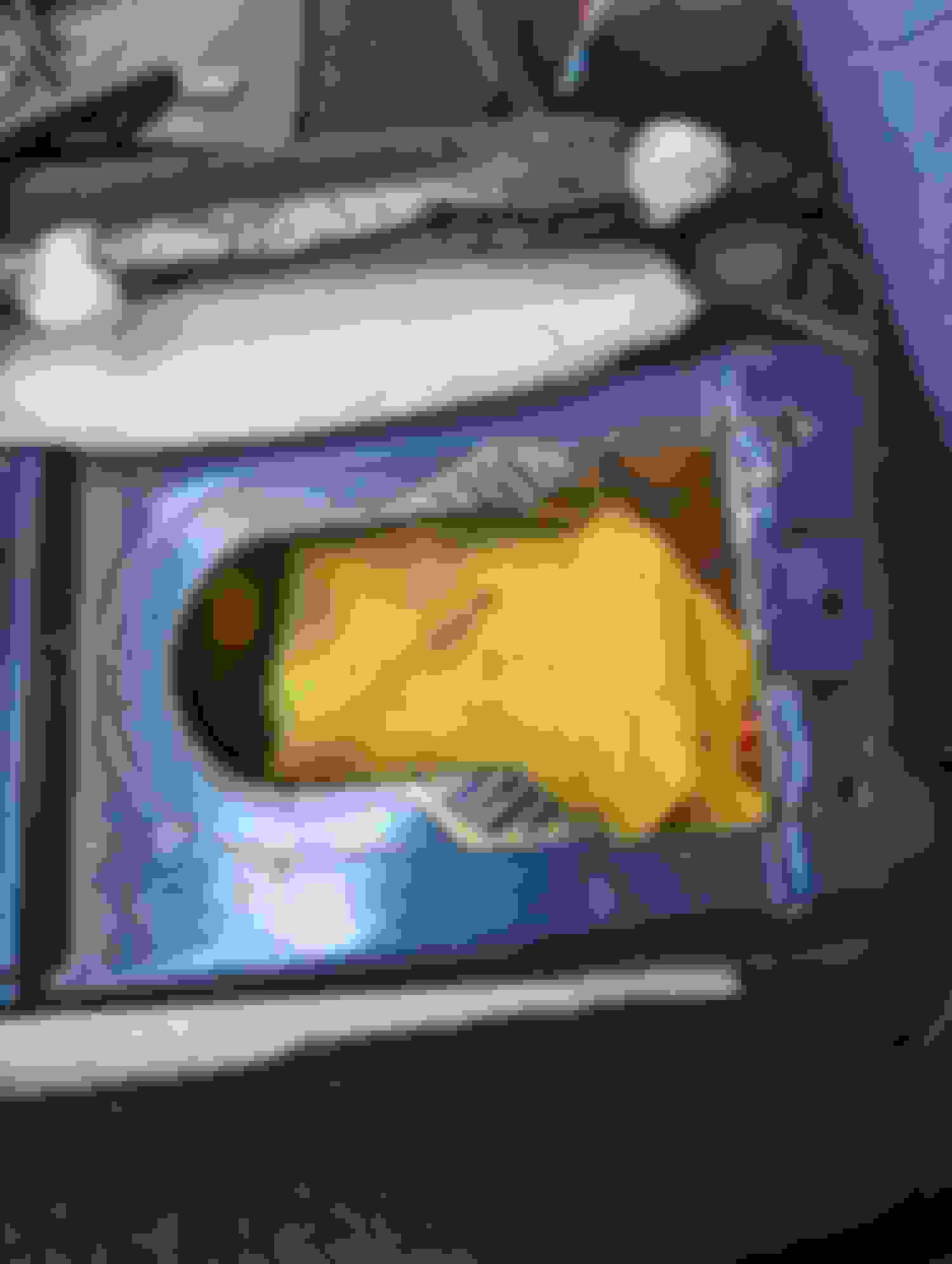
This took me a while to figure out. It�s good to have a friend with a manual car, so you can remove the console and do some measurements. There is some cutting involved. Your best friend here will be a rivnut tool. If you look closely at the area, you will notice spot welds where I suspect that the mounting points would be for handbrake as well as for the Yaw sensor. The MT car has a different layout and a wider tunnel, a slightly different harness, the yaw sensor is in a different location. If you leave it in its place, it will be too close to the handbrake for proper operation and needs to be moved forward quite a bit for proper function of the handbrake. I did as much measuring as I could on my friends� car. Using the actual MT console helps as well so that you can see where to line things up.
You do need to trim the bottom plate of the handbrake so that you are able to slide and mount it in its correct orientation. (The yaw sensor mount was in the way and if not trimmed you won�t be able to slide the handbrake forward.) For me I needed to move it over by a 1/8th inch to the left when I was done as the spring on the handbrake was rubbing on the cup holder ever so slightly. I basically used my measurements and compared to the locations of the spotwelds which happened to be within the correct orientation. From there, I drilled out the holes, flashed some paint and primer, and then went ahead to place the rivnuts. (It is easy to think that the handbrake belongs near the plate you removed to help take off the old line. It does not mount to that as when you go to test fit the console it will not fit.)
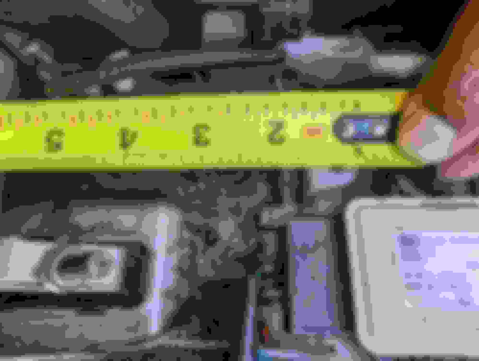
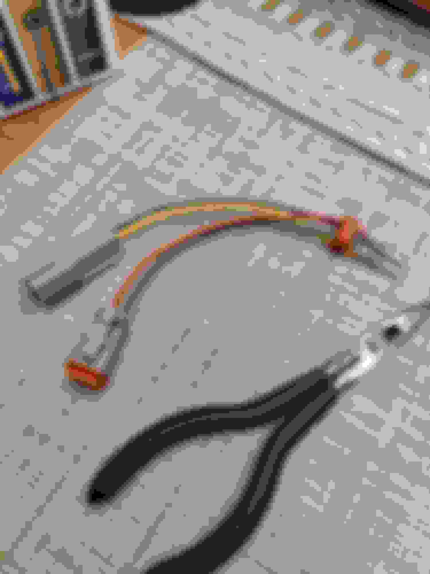
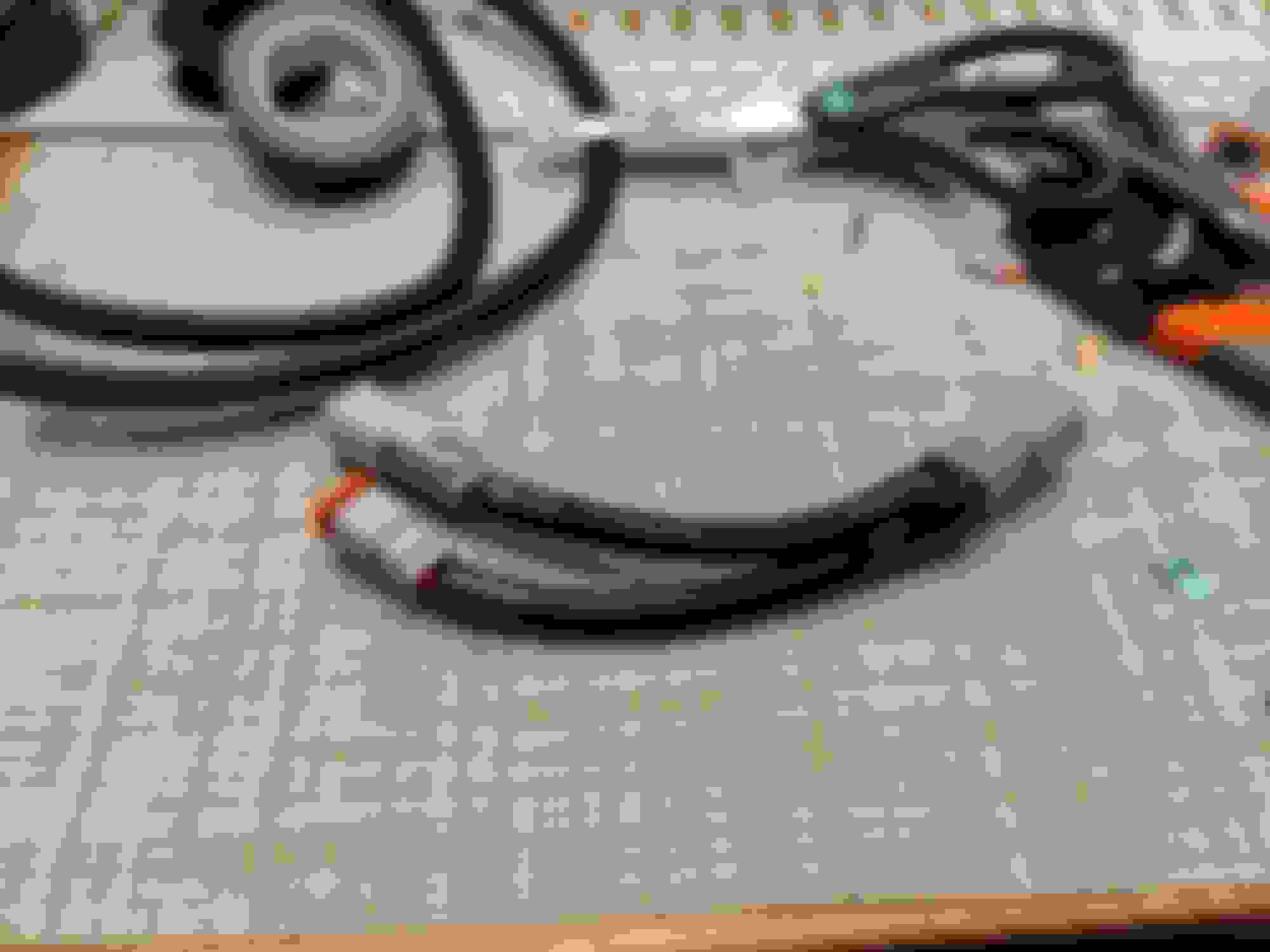
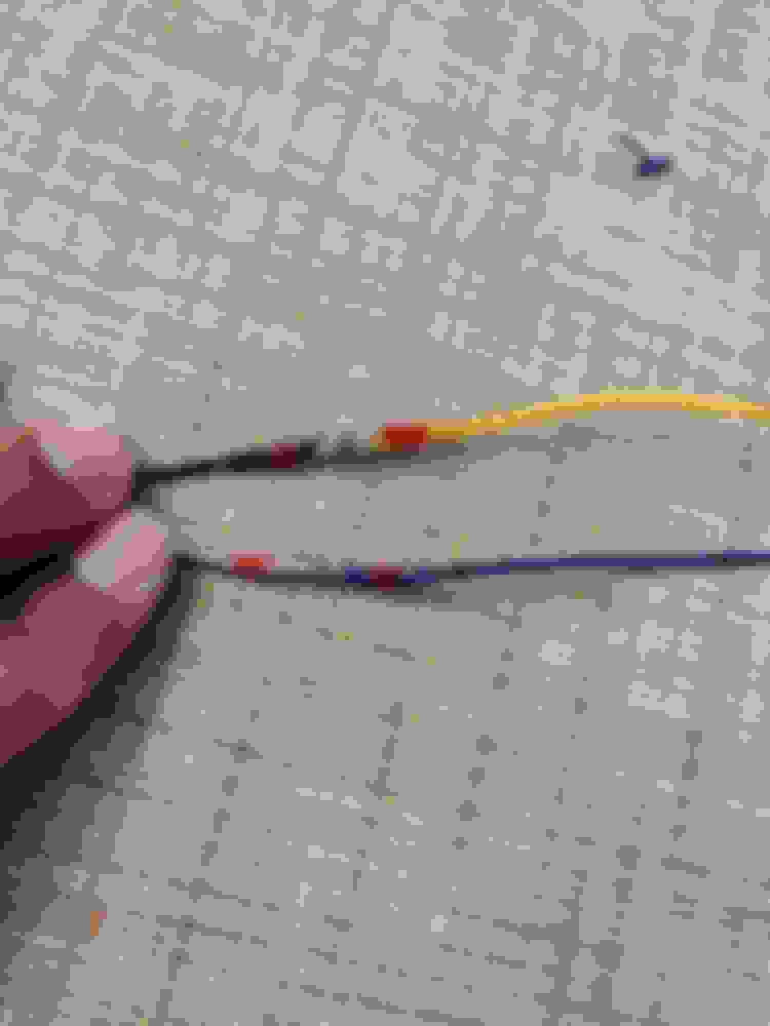
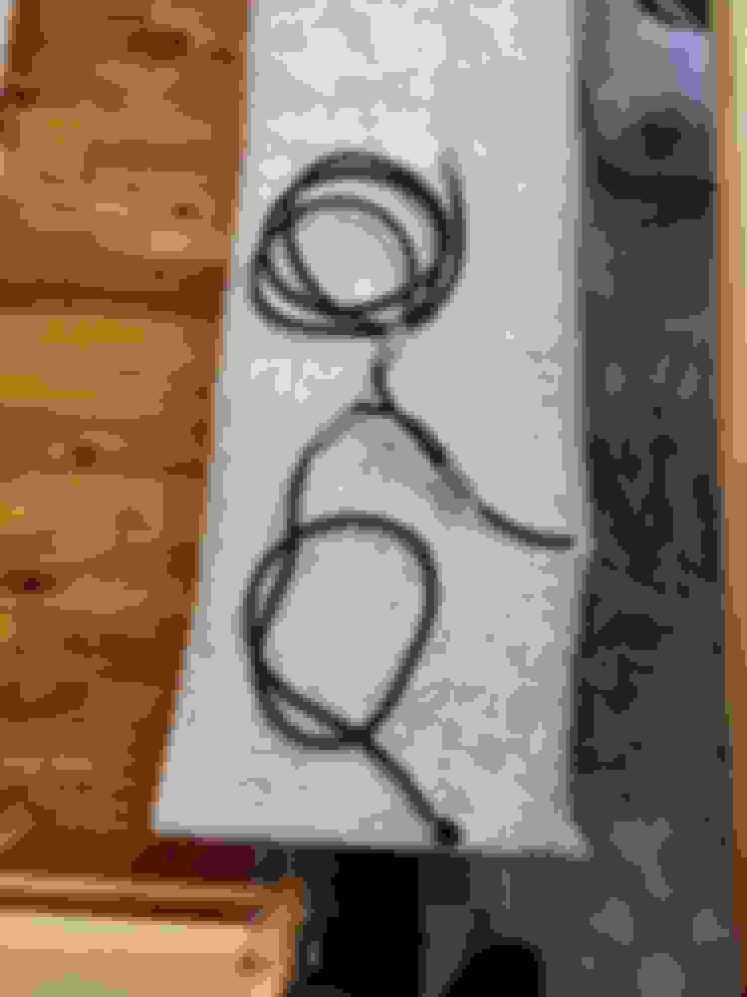
You do need to make a small cut on the tunnel to help fit the cable cover on the underside of the handbrake. You can re-use the plate from the old line if you saved it to cover up that hole. Once everything is in place you can slide the nylon grommet back into place and then reattach the bracket. You do not need to use the spring from the AT as the line is short enough and returned into place with actuation of the handbrake itself. (If you do buy a handbrake without the line attachment, you need to find one from a g37 coupe. The 370z line is too short and was making it difficult for me to line up the handbrake in its proper location.)
Notice the Size difference & lack of spring hook. Do Not Use 370z cable. it is too short. Must use g37! Friends car for reference point. Side view Notice the groove. AT doesnt have this. Distance from last ebrake bolt to air bag module bolt. Different Angle Distance between yaw bolt & E Brake bolt. This hangs over and is not flush. it is .25inchs Notice the BRAKE light cable on this side. Cutting on this line. This will work. In hindsight, I should have cut it a little but more to get as close to the yaw bracket as possible. Also could have came over a lil more to the left to avoid the cupholder. Making a cut for the cable cover under the ebrake. Put my nutserts in. There are 2 divots in this area roughly & within my reference measurements. Test fit Always! Cover up the holes with Aluminum Tape. Use the cover from the old e brake cable line to close this up.
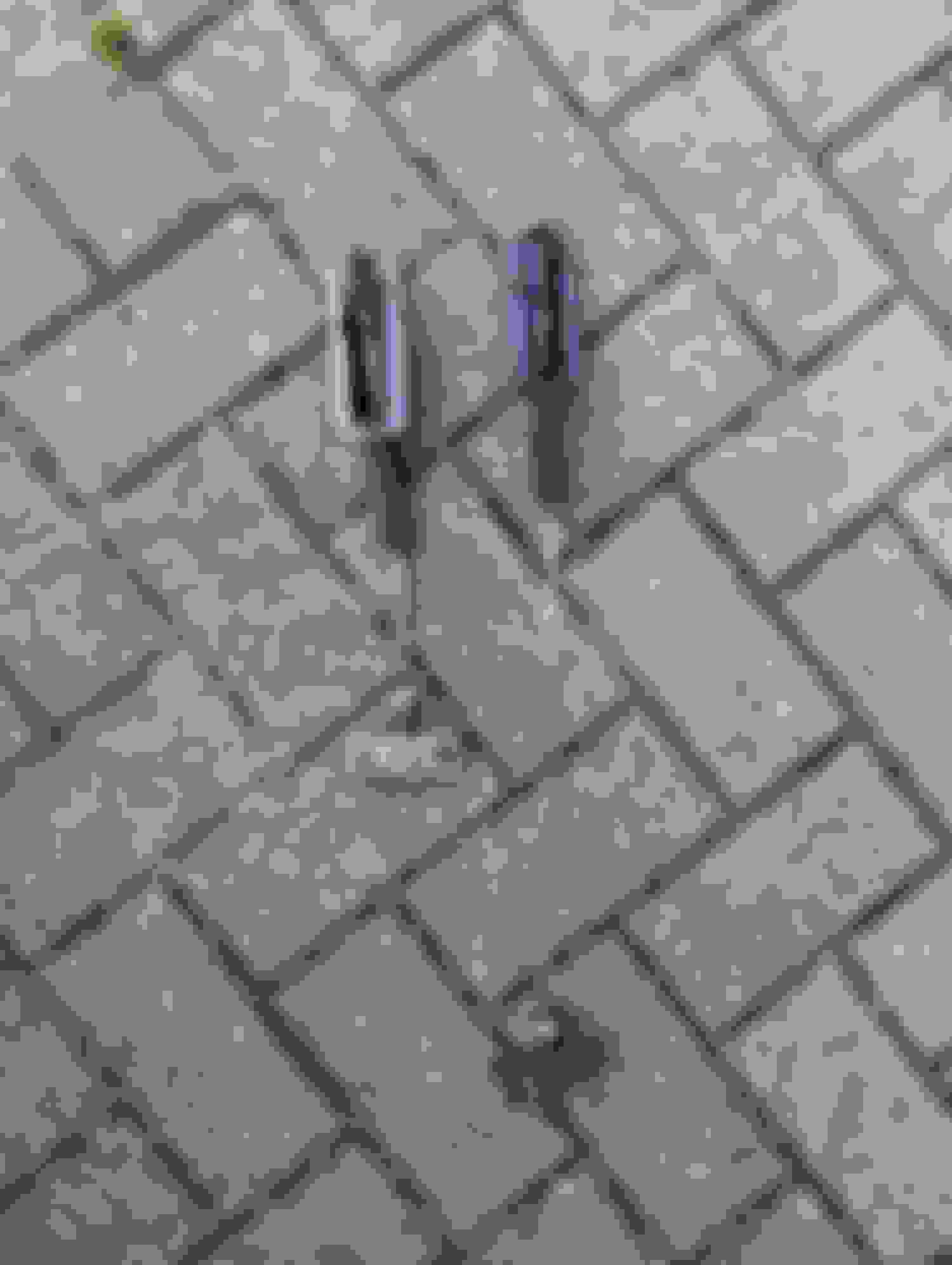
Yaw Sensor Relocation
On the manual car, the sensor is directly behind the shifter whereas on the auto it is about 5 � 6 inches back. ON the auto it is mounted on a bracket. You could cut it and move it forward and then reweld it but I did not want to go through that hassle. There are spot welds for where it could be but on the AT car the metal is contoured, and the sensor would not be set properly in place. There is a solution though and it requires using the 2 holes for securing the auto shifter, and a metal bar.
Start out by measuring the distance between the original yaw sensor bolt hole and the auto shift hole. It should be roughly 5 inches in length. I had some leftover steel bar that I cut at about a half inch bigger. You need to make 2 of these. Line up the holes on the bar, find the centers and mark them with a sharpie, and using a center punch mark you drill points on the bars. By doing this, you create a solid mounted area for the yaw sensor. You will need a small level to help the back end of the bar as it will need some shims to raise it slightly. By doing so the sensor will be level with the car as if it were in its original place.
I placed the holes for the sensor back about a half inch from its usual spot so that I can put in two rivnuts without having to drill into the car. This way it will be forward enough to not interfere with handbrake operation but out of the way for the shifter. Next cut the tape on the auto harness to help free up some of the wires for the yaw sensor. This will help create some slack in the line and help with placement. Pull it back about 3 inches so that the four wires are separate from the harness. You can now tape up the harness and the plug for the sensor individually and you can set the Yaw sensor in its final place. Yaw reference point with shifter. Not as close on the AT Using the original holes and mounting it to some tabs. Making sure it doesnt bump into anything. Marking it and moving it as close and as level as possible to the ridge. Put the nutserts in. Final Product.
Not as daunting as it may seem. I decided since I was waiting for parts to make a very clean wiring harness & sub harness. You do not need anything fancy but to just tap into 4 wires on the tcm, 2 for the clutch interlock switch and 2 for the reverse switch. I used Deutsch connectors and 20g wire to make it all look nice and pretty including some electrical tape, solder seal and some wire loom wrap. There are two ways to wire the clutch. Either from the pedal for OEM feel (pushing the clutch pedal in to start) or from the park neutral switch on the transmission itself (no need to push the pedal).
Before I started, I searched everywhere for pigtails for the interlock switch which I was unable to find. I did take the switch off the pedal (before mounting it). Carefully you can push in the tabs and take the switch apart. I then took the tabs and scratched the pins a bit and was able to put a small amount of solder on it. I then soldered the tabs to the wire and used some heat shrink to protect the tabs. If done right, you will be able to reassemble the switch with no issues and now you will have 2 wires running out from the back of the interlock switch You can then connect that end to a 2-pin connector and have the first part of the wiring done. I chose to run this wire up and behind the dash and down through the shifter opening.
The next pigtail for the reverse switch was available on CZP website. I ordered two just to have an extra. You can use the solder seal to extend the wires that come on the pigtail. I took some measurements with the new transmission to get an idea of how much wiring I would need for this loom. With that figured out you can go ahead and connect another 2-pin connector. I made a separate loom from the clutch interlock switch to the trans (from the pedal), one from the reverse switch to the trans and then made both of those connect into a 4-pin connector. This small Y piece of loom will be my sub-harness and will be helpful when I need to remove the trans in the future. Another 4-pin connector was then wired in directly to the tcm wiring.
For the Tcm wiring, you can cut the connector off as you won�t be needing it. I kept mine on until after I finished my wiring to ensure that I did not use the wrong wires. In the FSM you will see which wires you need to tap into for the car to work properly. Because mine was the 08 with the 5AT the wiring might be slightly different for cars with the 7AT. MAKE SURE TO CONSULT THE TM SECTION OF THE FSM FOR YOUR MODEL TO KNOW WHICH TCM WIRES TO USE. Continuing from here I used wires 5 & 7 for the reverse switch. 5 is the ground and 7 is the relay. For the clutch interlock switch I used wires 6 & 9 with 6 being the power supply and 9 being the relay. I suggest doing this before you put the trans back in as with the trans out the wiring is easily accessible. I used solder seal to help connect the wires. Tape & loom also used to help protect the wiring.
Because I used the Z1 CSC kit, I had to lengthen the starter cable wire, as the original harness would not fit with the slave cylinder now in the way. With the trans back in, I had run the harness over the right side and not on the left where it originally was. I also had to lengthen the cable from the foot brake to the hand brake position which controls the brake light on the dash, as well as lengthen the wires to the outlet in the arm rest. In the manual car, the power wires for the outlet in the armrest runs on the left side of the main harness. Since I had excess wiring from the center console I ordered, I went ahead and used that same wiring for the outlet to extend those wires.
You can get rid of the wiring from Ipod connector as it is in the way as well as get rid of the wiring for the AT shifter as it will no longer be needed. I have an AUX port and did not need to extend those wires, but it is a bit tight when you go to reconnect it to the console. Now I did not opt for a revmatch trans so I am not sure how that would be wired in. I also know that when you do this you will lose cruise control. For those of you that are tuned on an AT, you will need to get a new tune for an MT which also means a new license. You will be able to use the buttons to switch maps, but you will not be able to use cruise control or rolling anti lag. If you do have the Ecutek dongle you can map switch from your phone or the app.
CIS Switch. Good Luck Finding a pigtail! Took it apart to make a new a Pigtail. Deutsch Connectors ftw. Deutsch Connectors ftw. NEW CIS w/pigtail Y harness creation to TCM from CIS & Reverse Switch Done! Solder Seal ftw! New Harness! 08 Fsm with TCM wiring. Mine correlating to my wire choice. TCM plug underside. TCM top side. Thank god for color coded wires! Front view of new connector. Realizing my harnesses were too long, time to cut and solder seal. New Y harness. New Reverse Switch harness. Zip tying to mounting location. Providing enough slack and securing it in place. Extending the starter wire because csc kit is in the way. Final Product. Will make a plate to protect it. Extending the wires for the AUX. Extending the wires for the outlet in the armrest. Rerouted and in position.
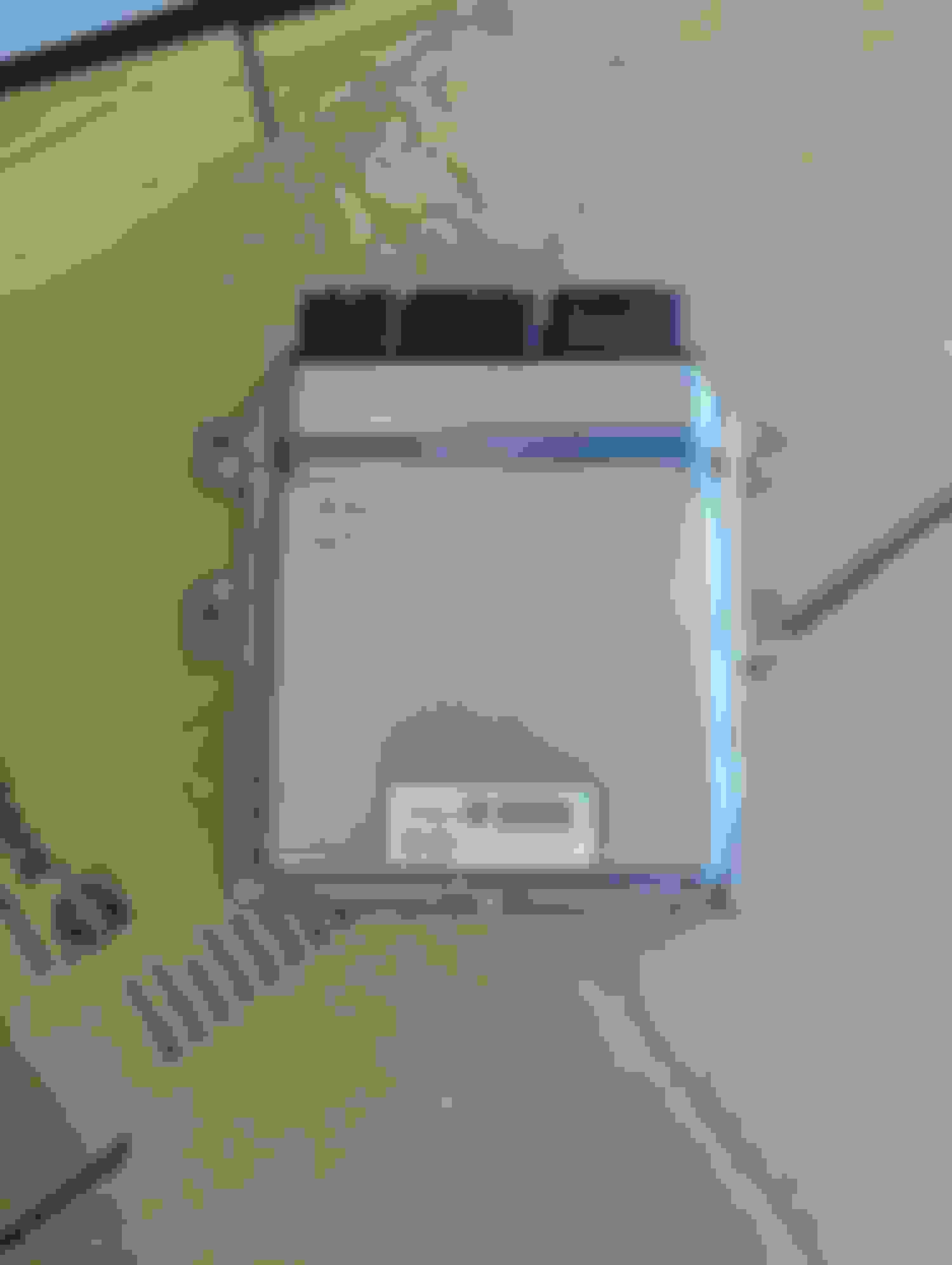
New ECU?
You can get a MT Ecu on eBay with key and bcm, but it is a little more complicated to get everything to work as well as not starting up right into limp mode. You can however get your Ecu �cloned� since it is already mated to the key and current bcm. For this I sent my ECU to Eugene at Enthusiast Auto Care. He was able to clone my AT info onto a newer MT ecu. I did lose my Uprev tune however as he did not copy it over to the new MT Ecu. However, I did pay for Ecutek and now have that software ready to be tuned instead. Since there is no real way to get Ecutek on a 08 G this was the next best thing. I did get back my old ecu and when I plugged in the new one & started the car, I had no issues. Remove it from under the passenger side. 08 ECU. Bye Uprev!
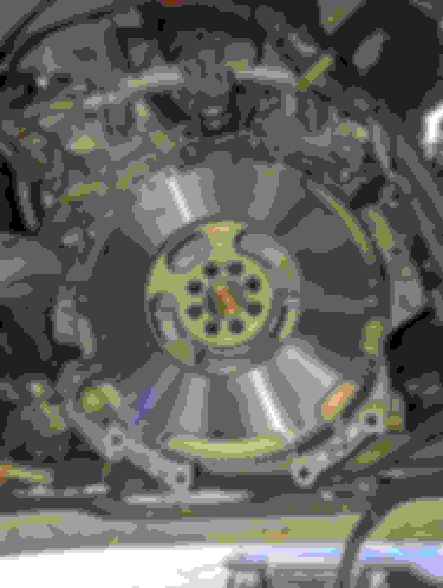
Installing the Clutch/Flywheel/Pressure Plate & Pilot Bushing
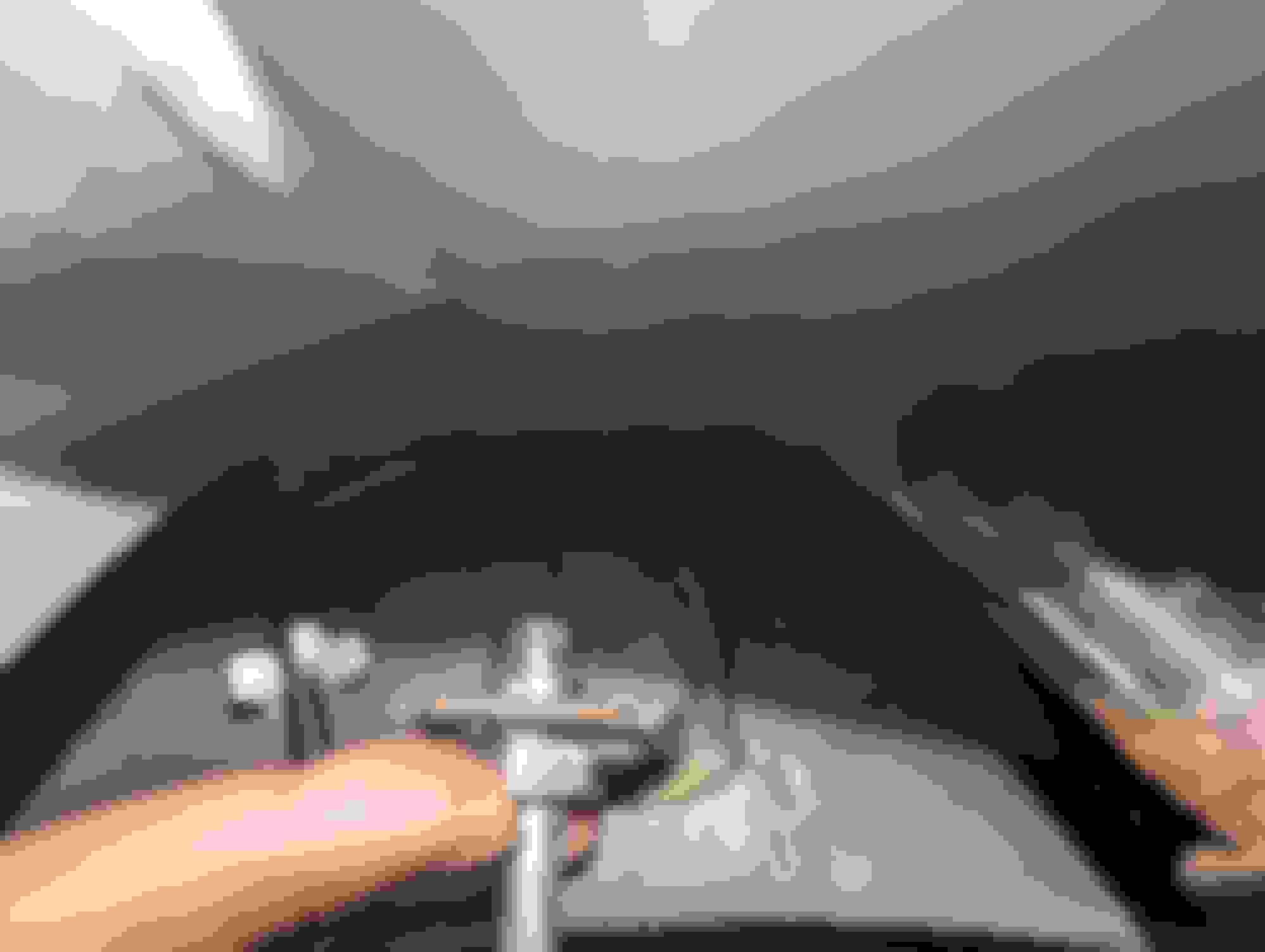
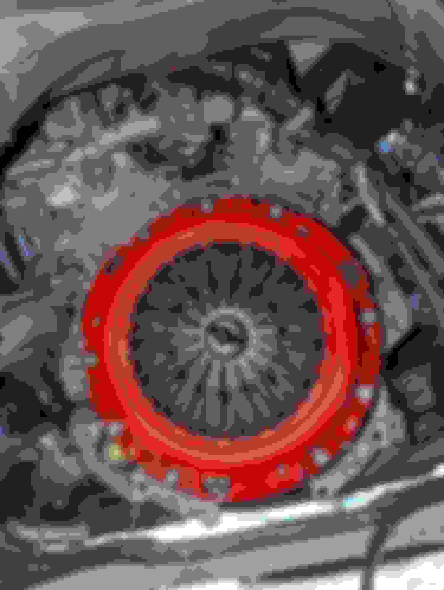
This one is straight forward. I went with the lightweight flywheel and unsprung clutch kit from Z1. You can use the OEM one or whatever you would like for your clutch and flywheel combo. I suggest using the correct OEM pilot bushing. Make sure to clean the recess of any bread or grease if you used it to remove the AT pilot bushing. With that clean you can put in the MT pilot bushing. I had a small mallet and a socket to help set and drive it in until it was flush. You do not need to send it all the way in. Next comes the flywheel. Make sure to clean it before install by removing the oil on the surface. The correct flywheel bolts are T55 bolts. Make sure you line up the flywheel and make sure that the little pin is lined up with the hole on the flywheel. It will not sit flush if you do not do so. Once that is in you can put some Loctite on and put all the bolts in. I had someone hold the crank so that I could torque the flywheel down as per the fsm.
Using the clutch tool install the clutch and then the pressure plate. Make sure that its surface is also cleaned before install. The pressure plate goes on in a specific orientation so make sure you match the dowels properly. I used some Loctite and again had someone hold the crank so that I can torque everything down to spec. Once done you can remove the clutch alignment tool and you are now ready to receive the new transmission.
14mm to tap in pilot bushing. do not bottom it out. Part 1 Part 2 Part 3
Installing the CSC Delete Kit (If you have it)
This one is also more straight forward than it seems. Because the CSC goes on the MT why not eliminate it with the new trans all together. I know some go with the CMAK as it is self-adjusting whereas the Z1 needs proper adjustment. It was easy to do however the slave cylinder adjustment was a bit tedious as it was my first time doing something like this. Also make sure you get the stack height before you install the clutch, flywheel, and the pressure plate. The Carizon�s YouTube page shows how to install this as a visual aid as well as call Z1�s customer support. As of now I do enjoy using the Z1 kit. Again, not necessary for the swap but I decided to go this route.
Removing the front cover. Putting in the new cover. & Pivot Ball & Arm w/throwout bearing. Slave Cylinder bracket. Slave installed on the car to make adjustments after trans was installed. Checking for clearance Better view.
Installing the Transmission & Starter
With everything done, it is time to put the new transmission in place. At this time, you can put in any new trans mounts as well as the crossmember. You need to reverse the process that was done to remove the trans. It should be able to slide right in with some persuasion. Make sure the dowel rods are lined up before the final push. Because I did this on the ground, I had to use my legs to push in the trans to its final position. If you get the trans within an 1/8 of an inch to mating, you can use the bolts to slowly bring it in evenly. Remember to add the vent tube back on top as well as the bracket for the tube back in its original place. All torque specs can be found within the FSM. I will note that due to the AT tunnel being narrower than that of a MT car, the extensions needed to address the bolts up top should be 3/8in. I used 1/2in extensions to remove them but was unable to get them to fit with the smaller gap in space. MT crossmember will then be lined up as the holes are already in place in-between the holes for the AT crossmember. Once this is done, remember to change or add any fluid that is in the MT trans before use. You can also go ahead and re install the starter as well as the service plates taken off when removing the AT. Shout out to the wife & to muscles to bring this back out form the basement and for pushing it in place! Lining it all up. Checking the other side. Not messing with this sensor. Lining up dowel pins. Just need it all the way in.
Now that the trans is in its place you can cut according to let the shifter fit. I went ahead and used lowered the trans jack a bit to let the trans and engine lean downward. I then covered the hole for the shifter and cut out an opening for it to fit in unobstructed. Remember to deburr and file any sharp edges. I also went ahead and used some primer and paint on the edges and when that dried, I used an aluminum tape to cover over the area. With this cut you can now put the transmission back up against the car and secure the crossmember in place.
You can go ahead and put the shifter in the car remembering to use the spring first. I did change the nylon busing to a new one and added some grease to it and the ball. You can then bolt the linkage and shifter together with the 12 mm bolt. You can then put on the plate and secure the three 10mm bolts up top to hold the shifter in place. If you bought a shifter and rubber boot assembly, you would notice that there is no room for the boot ring as you would have to make 4 holes to install it. Instead, you can use just the rubber boot. Go ahead and cut the rubber boot at the seams and you will get the inner and outer parts of the boot. With the inner part, you can make sure that it is placed properly over the shifter securing it in the recess. You can then use the outer boot and trim it to fit so that when you place it, it will overlap but not allow any liquid to be splashed inward.
The AT & MT mounting holes are all there. Just make sure to clean them before you send the bolts in there! Houston we have a problem. Went straight back to the ridge. Still didnt clear the bolt holes for the shifter. Made it wider but... Was still to wide. Going to full position warped the metal. When in doubt, Cut it Out! Thats better! Should look like this. Top View. Zip in the 3 bolts. Make sure to attach it to the trans. Boot is too big as At tunnel is slightly more narrow. Cut the boot in half. Using the bottom portion as it has a groove to fit in place. Should fit like this when notched. View form above.
Installing the New Center Console
This is easy. Just go ahead and put it back in. Make sure all your wires are connected properly and out of the way of any moving parts (Handbrake). You should not have to force anything in. It will fit into place like OEM because it is OEM.
Removed the cup holder because the e-brake was rubbing on it when activated. Hopefully I can get a shallower 3D printed one... Had to trim this as my e brake was a little too far back. 3M tape ftw to bring the key sensor in place for the back cover of the console. Drivers view of fit. Passenger view of fit
Bleeding the Clutch Hydraulic System
I did this by myself with a vacuum bleeder, funnel, and patience. At first it may seem like you are unable to get any movement. I filled up the reservoir slowly and slowly actuated the pedal with the nipple open on the bottom. When this wasn�t working, I went ahead and used the vacuum bleeder to pull all the air and fluid out through the nipple. Make sure you don�t pull all the liquid out of the reservoir and continue to add fluid as you do so. When done, you should have a nicely firm pedal.
Last piece of the puzzle here. Just follow the reverse to install it. I used a new 1-piece driveshaft instead of opting for an OEM MT driveshaft from a G coupe. The install was the same and I made sure to use some Loctite when securing the bolts & nuts to the flange. There is a recess on the DS, and it fits flush with the flange.
Final Piece of the Puzzle Driveline Officially Connected!
Startup & ECU Codes
When I started the car, I had 3 codes. C1109, C1102 & U1000. C1102 was because I didnt put in the left ABS sensor all the way in. C1109 is a voltage code. My Battery was not the best after having it since I got the car so I swapped my old red top for a new one. The U1000 is for the canbus iirc. When I fixed everything and restarted, all my lights turned off except for the key light. Afaik nobody has figured out how to get the key light off. I changed the battery in the fob but to no avail. Its not a big deal for me as I use it as a reminder now to remember to take the key with me. I have driven the car for a month straight (250 mi & counting) with no codes popping up & no issues yet.
Cost Breakdown
Before we begin, I will say that yes, I did splurge a �little� on new parts as well some things that I could have done without. I know in the beginning I said I was trying to be as cost effective as possible however with a total budget of 3k in mind. From what I gather most spend about 3k to swap to MT on a 370z but with an inflated economy & price gouging due to being in a post covid timeline my costs were not so nice. Some of the things I bought, I was going to do in the future anyway and since the car was going to be up for a while and be spiffed up, I figured why not do it now. I did buy most things on Z1 which I know a lot of these costs were bumped up with shipping and taxes. Also, miscellaneous runs to Advance Auto and Harbor Freight for tools or other quick items I needed added to the overall costs. My dog also decided to chew on my newly cleaned center console while I was gone for a few (blaming puppy energy & boredom) which led to me buying another shifter bezel and boot.
Total w/o misc items - $8083.90 / Total w/o misc items or z1 tax/shipping - $7026.21 / Total with everything $8748.15
Closing Thoughts
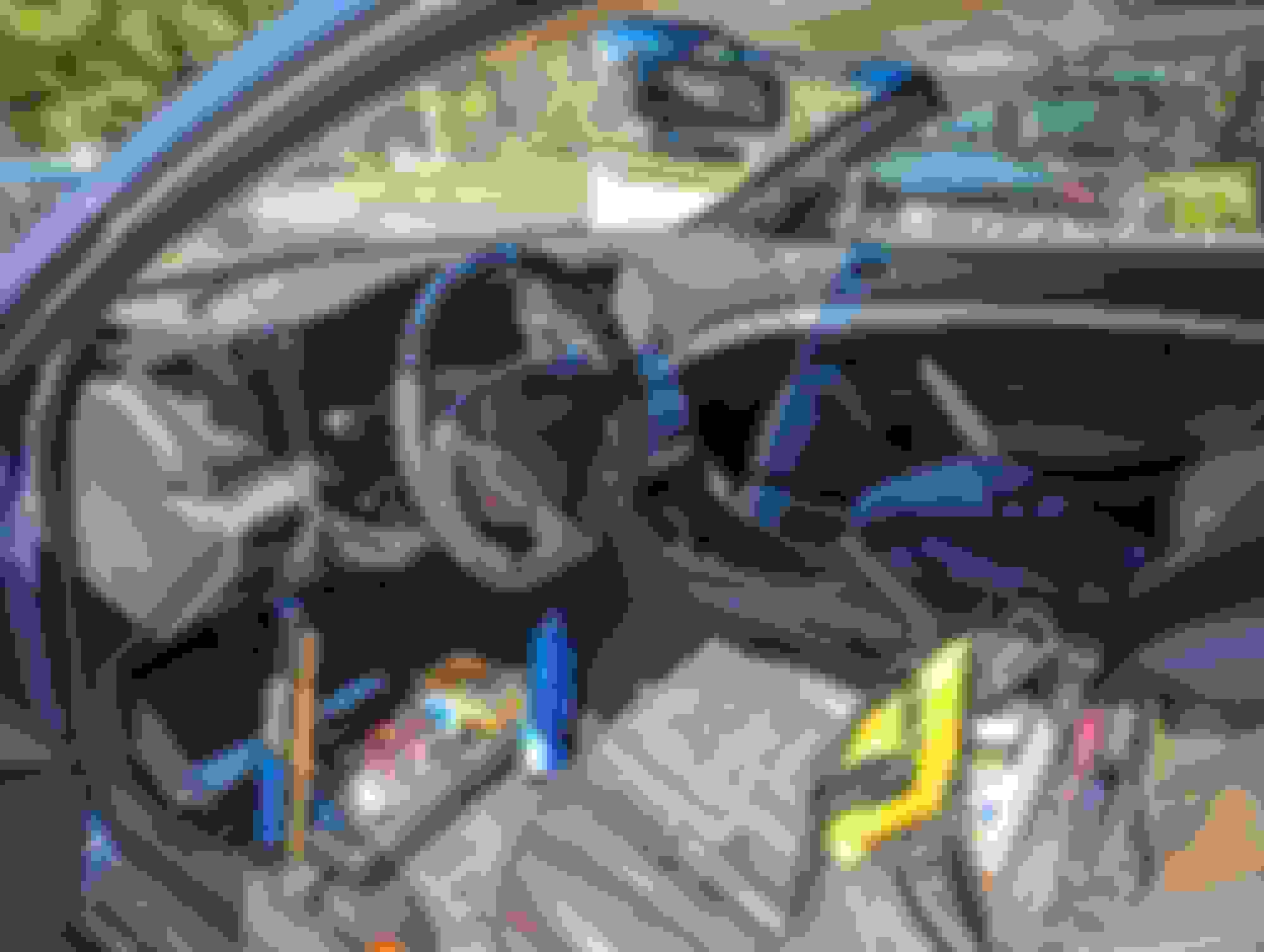
Now, that seems like a lot & quite frankly it was. I was not looking to spend that much when I decided to start this journey. While there is a somewhat small hole in my wallet that I am trying to fill as fast as I can there are some takeaways here. Yes, I will never make back any money if I decide to sell my car. Yes, it might have been cheaper & less headache to sell my car and buy one with a Manual. Yes, I went too deep. What I got out of it was priceless. I learned a completely new set of skills, I hit my goal of doing more involved work & being one step closer to my dream build, I have a new sense of appreciation for the car & best of all the smiles I get when I drive around town or blast through some twisty back roads. The sense of engagement when driving with a manual car cannot be replicated from an AT of any kind. That�s why, in my mind it was totally worth it. Best of luck doing this swap if you do so! Maiden Voyage as an MT. Cleaned up and looking like OEM Plus....
I had no idea it's that expensive lol, but good job and that is indeed an awesome learning experience and knowing that you did all that yourself is priceless!
Fantastic job. This will be stickier than that bud in the center console
All jokes aside you did an amazing job with the documentation of it all. You covered as much as you were able to find in all honesty.
Additional info:
For the clutch interlock connector, The AUTO I believe 2010+ come with 1 of these connectors for the Intelligent cruise control or Automatic Speed Controlling Device that could be sacrificed for this.
The only place I found online that carries it is Iwire (common in subarus)
As far as the Reverse Switch and Park/Neutral switch I have a batch of these that I use to convert Auto to MT harnesses.
I did not see any info on the A/T Detent switch for the automatic shifter.
Lights/codes:
Now the main reason why you have all of those remnant codes is BCM and all BCM. The BCM is registered to an AUTOMATIC vin. So upon start up the BCM will look for the TCM which since there is none will throw the U1000 for missing TCM can circuit. Being that there is no clutch interlock nor TCM the cruise wont work. However I've been informed that the last key to this puzzle is to reprogram your BCM from Auto to MT. This can only be done with Consult software. I requires a MT vin that will run your car. In theory a 2008 MT G37 or G35 BCM reprogram should work. Just now that the vehicle wont start after this programming. You will need to wire in the signal for the clutch interlock as well as the correct wiring for the cruise control cancel switch(brake switch) and in theory you should be golden. No U1000 and a working Cruise control
Again I have to applaud, not many have the resources and patience you have as well as the ability to put it all together as nicely as you did. You should feel proud of what you've accomplished.
Price wise this breakdown is great because it shows more of a MAX if you were to go brand new replacements. It can also show people where they could cut costs if they took the used/recycle option.
PS: in theory you can have ECUTEK in your car now that the TCM is out. It would require a 2010+ ECM NATS deleted and maybe swapping a few pins but it should work with the 2008 harness. Save that dipstick for folks here, many of them need it.

 09-01-2023, 11:48 PM


 )
)