When you click on links to various merchants on this site and make a purchase, this can result in this site earning a commission. Affiliate programs and affiliations include, but are not limited to, the eBay Partner Network.
Hi everyone, so now that I have been on winter break I decided to complete a project I had in mind for a little while, which is footwell LED's. I've already changed my dome and door lighting to LED's as the first mod upon purchasing the car, and this is meant as a complement to that.
I've always been jealous of my dad's GS350 with it's accent footwell lighting on both the front and rear footwells, so I set out to do it myself for the G. The goal of this was to accomplish the fade-in fade-out effect of the map lighting, which could not be accomplished by tapping into the fuse box. In total, it took me perhaps 5 hours plus time for a lot of research, which you won't have to do if you follow this! I would rate this a 4/10 difficulty, harder if you do not have basic electrical wiring experience. Probably the hardest part is squeezing yourself into the footwells time and time again!
Disclaimer: I did this on a 2007 G35. As the wiring is almost exactly the same it should work for all G37's and probably also the Q's. I checked the FSM for a 2013 G37 as well and it is the same so I am 99% sure it will work. Also, be careful with a soldering iron, working in the footwells of the car is very tight!
Part Zero: Supplies
First off, you're gonna need some supplies. You can choose to do it a different way, but this is what I got:
- Sockets make the system more modular and easier to wire up. If I want to, I can easily swap out a bulb.
18-22awg hookup wire, at least 20 feet - The wire gauge doesn't really matter here as we are using very low current LED's, but a thicker wire is harder to deal with. Make sure to get red/black wiring that splits so it is easy to keep track of. Also, 20 feet is probably overkill but it is needed if you mess up, or need slack to help you thread wires.
Electrical Tape, any
Knife or Scissors
Wire Cutters + Strippers - crimping is an alternative to soldering in areas that have a one way- connection
Soldering Iron with 60/40 solder - optional as you can use a bunch of wire taps, but makes it a lot easier and more secure imo
Multimeter or Battery Tester - you can also use the LED's themselves to test, but this requires re-connecting and disconnecting the vehicle battery multiple times and is a hassle
Light Source - I used my iphone, a small LED light would be ideal
Straightened Wire Coathanger for threading wire
Part One: Starting Off
Once you have all of these compiled, the first step is to disconnect the vehicle battery. I don't know for sure, but I would think we don't want to be messing with the BCM with the battery still connected. Pop the hood and pry open the battery cover. Loosen the nut on the negative battery connector with an adjustable wrench and take it off. Tuck it to the side of the battery so it doesn't accidentally reconnect.
Now, move inside to the passenger footwell. You first have to unscrew the black fastener on the deep side of the footwell:
Now, look at the trim piece directly adjacent to the kick plates. There are 4 clips holding this in. Get your fingers under it, and pull directly up:
This picture is of the drivers side, but it is exactly the same on the passenger side. Sometimes the next piece covering the BCM will come off with this piece as it did for me, but if not simply pull that piece off towards the seat. You will be left looking at the BCM. Unfortunately I didn't remember to take a picture but you will definitely see a rectangular box with a mass of wires and plugs coming out of it.
Part Two: BCM
For this wiring project, we are focusing on the TOP LEFT white plug:
Looking at this plug, the pins we need are the RED 11 PIN and the PURPLE/LAVENDAR 19 PIN. They are on opposite sides of the plug:
Next, we need to tap these wires. Be careful not to yank on them as they are very thin (I would guess 26 awg), and would be a nightmare to replace if they broke. Pop the connector out. This may be hard, but what I did was use one screwdriver to push in the white tab and one flathead to pry out the connector. You can practice on one of the other more easily accessible connectors if you wish. Once they are out you should cut the black sheath around the wires to give yourself better access to the wires.
Traditional wire taps may not work as these wires are so thin. I have read elsewhere some people have used posi-taps, but I couldn't find any locally and didn't want to wait for an online order so I went ahead and soldered it. To do this, I first melted the insulation off of the wires with the soldering iron. The wires are so slim and hard to access a wire stripper would have been impossible. Once it is melted off of the top and bottom, you can easily pick off the remaining insulation with your fingers or with a knife. With the bare copper wire, you can now solder a length of the hookup wire to the BCM wires. Wrap the solder joints in electrical tape.
RED ON YOUR HOOKUP WIRE GOES TO THE RED WIRE ON THE BCM, PIN 11
BLACK ON YOUR HOOKUP WIRE GOES TO THE PURPLE WIRE ON THE BCM, PIN 19
For some reason the way the interior lighting works is with a constant 12V source, the red pin 11, on positive and a rising ground on the purple pin 19. As the ground rises up to 12V, the voltage difference reduces, so the lighting dims and eventually turns off. Strange but this is just how it works.
Part Three: Wiring the front LED's
Test this length of wire with your multimeter and the BCM plug reconnected to make sure you're getting a 12V reading with the doors open and battery reconnected. If it's good, we can move on to routing and connecting the rest of the wiring.
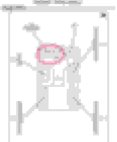
Before you proceed, make a mental image of the wires you're going to have to route. From the passenger footwell, we're gonna need one going behind the dash to the drivers footwell. Use the hole in the picture below, I used the coathanger trick to pass a 4-5 foot section of wire through. Remember to be generous because if you don't have enough wire it will be hard to solder, and you'll have to extend the wire. You can see the hole next to top of the gas pedal as well as the wire I passed through:
This section of wire must also be soldered to the wire that you tapped into the BCM with.
Now that we have working wiring on both the passenger and driver footwell, solder the LED's on. Don't mount them yet, because you will need to do the wiring for the rear footwells. However, you can test them out by reconnecting the battery if you wish.
Part Four: Wiring the Rear Footwells
This part is up to you, as doing the rear footwells doesn't have as much of an effect as the front. Still, I wanted to do the entire car. To pass wire through to the rear, you need to use the coathanger trick again. This will likely be tougher than the behind-the-dash hole. Try to start from the back, and pass the wire forward to the front side of the seat.
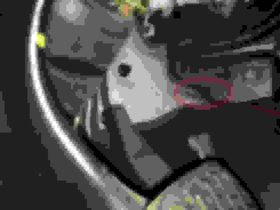
In order to route the wire in which it is minimally visible you're gonna have to get the wire to come out to the left hand side of the seat(for drivers side) or the right hand side of the seat(for passenger side). Make a small incision with a knife and route the wire through it. You can reach under the carpet as you have removed the trim piece on the door sill earlier:
The picture above I took after I was done, when actually routing the wiring you will have to run it under the trim piece you removed:
This is also where I stored the excess wire I had, there was enough space. Make sure not to put the wires where the white clips would go. Also, be careful not to pull the wiring so much as to pull the wire back under the seat from the rear of the car, as you would have to do the coathanger trick again.
Solder the rear bulb onto the wire and tape it down. It's not the best solution but no one will be able to touch the bulb so deep under the seat, and the electrical tape is sticky enough to keep it in place.
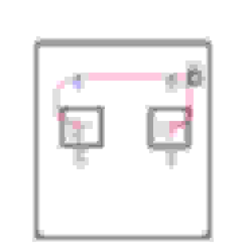
The final wiring should look like this simplified diagram I drew in paint, lol:
Note the blue circles are the LED's, the red lines are the wiring you will lay down, and the green are the solder joints. The passenger side footwell will have a FOUR way solder joint. This diagram doesn't show that the wire consists of both the positive and negative leads, and you must solder them each separately. Make sure to wrap the solder joints in electrical tape.
Part Five: Cleaning Up
Once you have the rear LED's secured, you can pull up the excess wire and store it under the kickplate trim piece, as I said earlier. Now is when you can secure the front LED's. Here is something I did on the front drivers side footwell, make sure you are well clear with the wiring of any of the pedals. After taking this picture I added a lot of zip ties to make sure of this:
The passenger side footwell is a lot easier as there are no pedals and there is a convenient metal hook you can attach your LED to. Make sure to tuck the wire slack away. After you are done, re-attach the trim pieces and admire your work
Part Six: Results!
I used blue LED's throughout. You might want to just use standard white, or another color. Also, if my carpet wasn't so worn (and dirty, haha) I feel I would get an even better light coverage:
Of course, this DIY isn't perhaps the best method and if you find a better technique during any of this let me know! I'd also be happy to answer any questions people have! And I if I made any mistakes or left out some instructions please let me know.
Cool project and nice writeup!
I am a huge fan of Posi taps and locks, but they are a pain to find locally. Posi-taps would be just as secure, but no soldering and the wires are not ruined like normal taps, which sever the wire.
I just received my first order from a Japanese company who had the lowest pricing I could find ($20 min order, though), and they came in 2 weeks, IIRC. Eastern Beaver
PS. Your link to the LEDs points to the led buckets.
Nice write up, very informative and thorough. One thing I'd change would be routing the wires behind the steering linkage, but got to have something to pick at, lol. I'm going to copy this and put it in the DIY folder, thanks for the contribution!
Nice work!
I'm thinking I'd like the footwell lights to be on while driving. The footwells always seem like a black hole to me when the dash is on.
Maybe key them to the headlights to have them on at night? Or maybe tap them to something that is active when the dash is in night mode?

 12-28-2015, 09:38 PM