Brake Cooling Ducting...
#31
Thanks for the template John I am going to get working on this. That other guys said to cut a hole through your wash tank. I am like you I will just take it out when I am going racing. In the mean time RainX the **** out of your window. Thats what we do on our 24hr of Lemons race car.
Once I get to routing the hose I will take pictures and post them up for everyone. I am so excited LOL
Once I get to routing the hose I will take pictures and post them up for everyone. I am so excited LOL
#33
Thanks for the template John I am going to get working on this. That other guys said to cut a hole through your wash tank. I am like you I will just take it out when I am going racing. In the mean time RainX the **** out of your window. Thats what we do on our 24hr of Lemons race car.
Once I get to routing the hose I will take pictures and post them up for everyone. I am so excited LOL
Once I get to routing the hose I will take pictures and post them up for everyone. I am so excited LOL
Good Luck and welcome
#34
I did something similar to MaxToTheG37, however to accommodate 3" OD brake duct, I did make an opening for the duct to fit. I have already Rivet-ted them so I will post more pictures when I get back home.


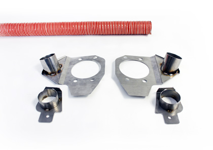
Also I have finished making splash guards to mount them to cool the disc rotors directly.

Also for your reference


Also I have finished making splash guards to mount them to cool the disc rotors directly.

Also for your reference

Looks pretty close to me!!! Stillen Kit:

Last edited by TVPostSound; 04-13-2012 at 02:51 PM.
#36
Actually there will be only two issue. The Pipe coming off splash guard is too long.
1. Will rub G37 lower wishbone at full opposite lock, if it is longer than 1 1/2".
2. The pipe coming off the splash guard is too far from center. This will cause imbalance on rotor outer face and inner face temperature.
You never want to blow cold air onto rotor face. Rather closer to center hub as possible.
Similar only difference is our car has less of space at the back. I guess our chassis are wider so very tight when running duct behind the coilover.
#37
Well I have all my parts and just have to finish fabricating the rotor mount and I should be ready to go. I think all total I am in it right now for just a bit over $160.
I hope to start installing and taking pictures for everyone to show how I routed the hose. I believe for the passenger side you are going to have to remove the washer tank which is no biggie. Thanks to joo030879 (aka John) for the template. I would have been working on that forever I believe.
I hope to start installing and taking pictures for everyone to show how I routed the hose. I believe for the passenger side you are going to have to remove the washer tank which is no biggie. Thanks to joo030879 (aka John) for the template. I would have been working on that forever I believe.
#38
OK here are my pictures from what I did on mine, thanks to having a template made this much easier. After I was done I was rotating the wheel to see about any rubbing and I wasn't watching where my fingers were and I got my middle finger pinched between a spoke and a brake caliper. Needless to say my finger lost. I broke the tip and about sheared the tip off. So now I got 6 stiches and a damn splint LOL.
Anyways here are my pictures
This is the intake before I painted it


Then it is painted and installed in the car


Then back plate mounted with 2.5in adapter for hose

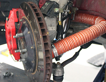
Then I hooked up hose and ran it back above the lower control arm. You must make sure that it is zip tied up as high as it will go to aid in not rubbing. You will also need to remove your windshield washer bottle to aid in the installation unless you want to hack it up like the other guy did.


Once again thanks to joo for the template. This for the right side but the left is much easier. You can reach everything by removing the wheel wells. This should work nicely. I am into it for around $175 or so. I have part numbers and suppliers if you want to PM me.
Anyways here are my pictures
This is the intake before I painted it


Then it is painted and installed in the car


Then back plate mounted with 2.5in adapter for hose

Then I hooked up hose and ran it back above the lower control arm. You must make sure that it is zip tied up as high as it will go to aid in not rubbing. You will also need to remove your windshield washer bottle to aid in the installation unless you want to hack it up like the other guy did.


Once again thanks to joo for the template. This for the right side but the left is much easier. You can reach everything by removing the wheel wells. This should work nicely. I am into it for around $175 or so. I have part numbers and suppliers if you want to PM me.
#39
OK here are my pictures from what I did on mine, thanks to having a template made this much easier. After I was done I was rotating the wheel to see about any rubbing and I wasn't watching where my fingers were and I got my middle finger pinched between a spoke and a brake caliper. Needless to say my finger lost. I broke the tip and about sheared the tip off. So now I got 6 stiches and a damn splint LOL.
Anyways here are my pictures
This is the intake before I painted it


Then it is painted and installed in the car


Then back plate mounted with 2.5in adapter for hose

Then I hooked up hose and ran it back above the lower control arm. You must make sure that it is zip tied up as high as it will go to aid in not rubbing. You will also need to remove your windshield washer bottle to aid in the installation unless you want to hack it up like the other guy did.


Once again thanks to joo for the template. This for the right side but the left is much easier. You can reach everything by removing the wheel wells. This should work nicely. I am into it for around $175 or so. I have part numbers and suppliers if you want to PM me.
Anyways here are my pictures
This is the intake before I painted it


Then it is painted and installed in the car


Then back plate mounted with 2.5in adapter for hose

Then I hooked up hose and ran it back above the lower control arm. You must make sure that it is zip tied up as high as it will go to aid in not rubbing. You will also need to remove your windshield washer bottle to aid in the installation unless you want to hack it up like the other guy did.


Once again thanks to joo for the template. This for the right side but the left is much easier. You can reach everything by removing the wheel wells. This should work nicely. I am into it for around $175 or so. I have part numbers and suppliers if you want to PM me.
Here is sample of what I am working on right now. Also taking a good look at your pictures. make sure not to blow cold air onto rotor face. Rather keep it centered toward the top hat. Other than that, your duct looks lot cleaner than mine. Well done.

#40
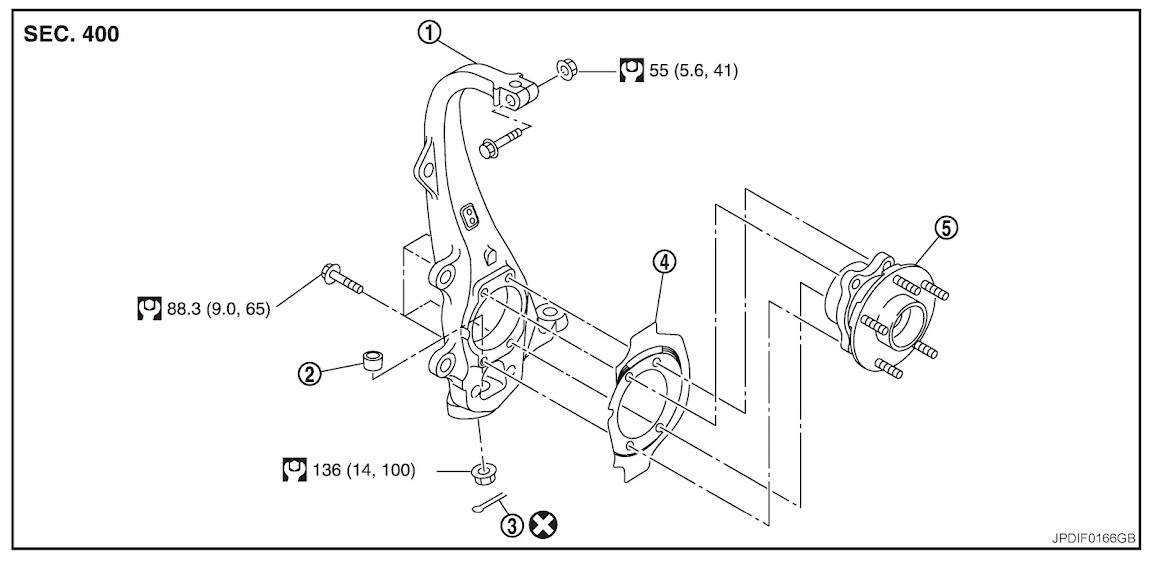
The duct is about half and half when pointing on the rotor. The only way I see to make it pointed at the top hat would be to extend the metal that holds the adapter so as to make a better bend. On the way to work today I noticed my slip light and traction control lights remained on (didnt do it while driving around the neighborhood). When I got to work I shut car off and then turned it back on and the lights went off. I might have to trim the metal away from the sensor that is mounted on the spindle. I think that might be my problem
#41
The duct is about half and half when pointing on the rotor. The only way I see to make it pointed at the top hat would be to extend the metal that holds the adapter so as to make a better bend. On the way to work today I noticed my slip light and traction control lights remained on (didnt do it while driving around the neighborhood). When I got to work I shut car off and then turned it back on and the lights went off. I might have to trim the metal away from the sensor that is mounted on the spindle. I think that might be my problem
Instead of bending and fitting. Best way IMO is instead of 3" OD pipes. Go with 2 1/2" or even 2" pipes and hoses.
#42
I pulled the sensor that went inside the wheel hub so I hope that isn't it as the hose mount to the hub was pretty close to that. I do remember that I put speedbleeder on the calipers so I bet that I am a bit low on fluid, I will check when I get home from work today but I betcha that is it as I forgot to fill it back up till now. lol
EDIT: just went out to parking lot and yep I am in between max and min on the reservoir. Hopefully this will clear all the lights
EDIT: just went out to parking lot and yep I am in between max and min on the reservoir. Hopefully this will clear all the lights
Last edited by toyzforme; 04-26-2012 at 02:40 PM.
#43
I pulled the sensor that went inside the wheel hub so I hope that isn't it as the hose mount to the hub was pretty close to that. I do remember that I put speedbleeder on the calipers so I bet that I am a bit low on fluid, I will check when I get home from work today but I betcha that is it as I forgot to fill it back up till now. lol
EDIT: just went out to parking lot and yep I am in between max and min on the reservoir. Hopefully this will clear all the lights
EDIT: just went out to parking lot and yep I am in between max and min on the reservoir. Hopefully this will clear all the lights


