
Review Fixing Tachometer (RPM Gauge) and Warning Lights
 08-18-2013, 07:23 AM
#1
Administrator

Thread Starter
Fixing Tachometer (RPM Gauge) and Warning Lights
Well if you ever decide to swap your engine out or even swap your ECU to a non-plug and play standalone ECU, your instrument cluster (dash) will experience two things:
1) RPM & Water Temp Gauges that don't work
2) A dashboard lit up like a Christmas Tree.
I was also sick of having useless paddle shifters so I figured I'd get rid of them too. Let the surgery begin!

Pulled the who dash out:


See back in the good old days, the dashboard would have a few pins, and Nissan would provide a pin diagram telling you which gauge each pin triggers. Nowadays however, it is all digital. The CAS tells the ECU how fast the engine is spinning, the ECU sends a digital signal to the Unified Amplifier, and the Amplifier sends it to the dash. We had to pull the dash apart to see if we could intercept any sort of wire to the RPM Needle Motor.

As you can see, tracking down the circuit board lines was a nightmare.
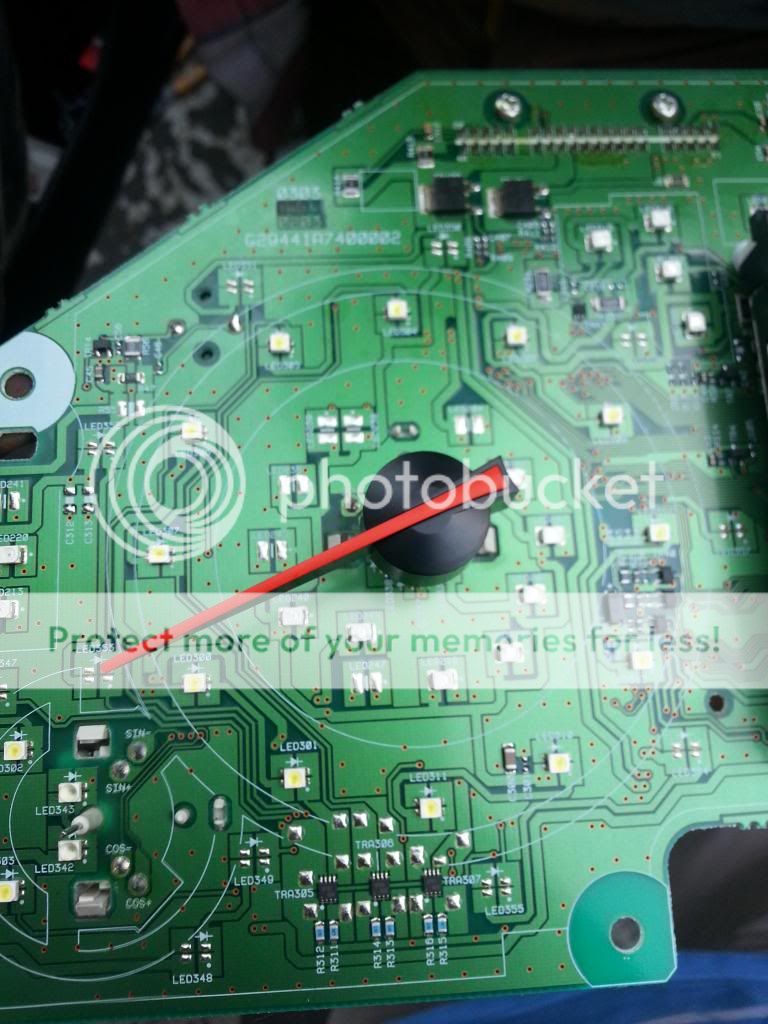
Removed the motor cover and here we are, at the heart of the motor! Two coils -> Four Pins labeled sin+,sin-,cos+,cos-.

Took it to an electrician and soldered a wire to each pin, now all we have to do is fiddle with the inputs to these wires to get the RPM needle to work.

And while the dash was open, all the warning lights were blocked off, looks nice and OEM now!

To be continued..
1) RPM & Water Temp Gauges that don't work
2) A dashboard lit up like a Christmas Tree.
I was also sick of having useless paddle shifters so I figured I'd get rid of them too. Let the surgery begin!
Pulled the who dash out:
See back in the good old days, the dashboard would have a few pins, and Nissan would provide a pin diagram telling you which gauge each pin triggers. Nowadays however, it is all digital. The CAS tells the ECU how fast the engine is spinning, the ECU sends a digital signal to the Unified Amplifier, and the Amplifier sends it to the dash. We had to pull the dash apart to see if we could intercept any sort of wire to the RPM Needle Motor.
As you can see, tracking down the circuit board lines was a nightmare.
Removed the motor cover and here we are, at the heart of the motor! Two coils -> Four Pins labeled sin+,sin-,cos+,cos-.
Took it to an electrician and soldered a wire to each pin, now all we have to do is fiddle with the inputs to these wires to get the RPM needle to work.
And while the dash was open, all the warning lights were blocked off, looks nice and OEM now!
To be continued..
Last edited by G37Sam; 08-19-2013 at 05:20 PM.

The following users liked this post:
timp (08-18-2013)

The following users liked this post:
G37Sam (08-31-2013)
09-11-2013, 08:43 AM
#3
Administrator
Thread Starter
We're getting somewhere:
 09-26-2013, 06:58 PM
#5
Administrator
Thread Starter
After a lot of fiddling and playing around, we decided to ditch the OEM stepper motor. Got an aftermarket one that's a lot more sensitive and responsive. The current motor was desoldered out and a new one is coming in. Best part is: we get to keep the OEM needle. I'll keep you guys posted.
PS: Do not attempt to run the OEM motor at 12V's. You will end up with a blown dash. Don't ask me how I know.
PS: Do not attempt to run the OEM motor at 12V's. You will end up with a blown dash. Don't ask me how I know.
The following users liked this post:
mikey_mike (06-21-2014)

Thread
Thread Starter
Forum
Replies
Last Post
redlinernyc
Engine, Drivetrain & Forced-Induction
10
02-29-2016 11:06 PM
inspector94
Engine, Drivetrain & Forced-Induction
8
09-08-2015 12:57 PM