
Vendor Betty’s Garage grounding wire kits v. 2.0

What do you do when you have the best? You make it better! I mentioned some time back in my original vendor thread that I’d be increasing the price of my grounding kits. What I didn’t mention then is that there’d be a significant upgrade as well.
So here it is: Introducing Betty’s Garage grounding wire kits version 2.0.! In addition to the original wire set the new version now adds grounding for both throttle bodies. Why? Because directly grounding the throttle bodies improves throttle response of the drive by wire system in our G37s. It’s an 8 AWG cable from each TB merging to a single connector at the negative battery terminal. The TB ground wires are 8 AWG on both 4 and 8 AWG sets. 8 AWG is more than overkill, 16 gauge speaker wire would be sufficient but I made it 8 for continuity. The kits are still offered in the same colors: black, carbon fiber, red, blue, and white. Or you can order a custom color to be unique if you’re willing to wait a little longer for production.
The email address to reach me and to send PayPal payments is bettysgarage@earthlink.net. I am now able to ship same or next business day in most cases. USPS Priority Mail shipping is still the standard method but other methods including UPS are now available; if you prefer a different method be sure to let me know when placing your order.
When placing an order, be sure to send me a PM or email (bettysgarage@earthlink.net) with all the following information: your name, screen name, what color and size kit you'd like, what year and model G you have, and your shipping address if it is different from the one PayPal will give me.
Lastly thanks to all of you who’ve supported, bugged, encouraged, and inspired me in this endeavor. Your support means a lot to me.
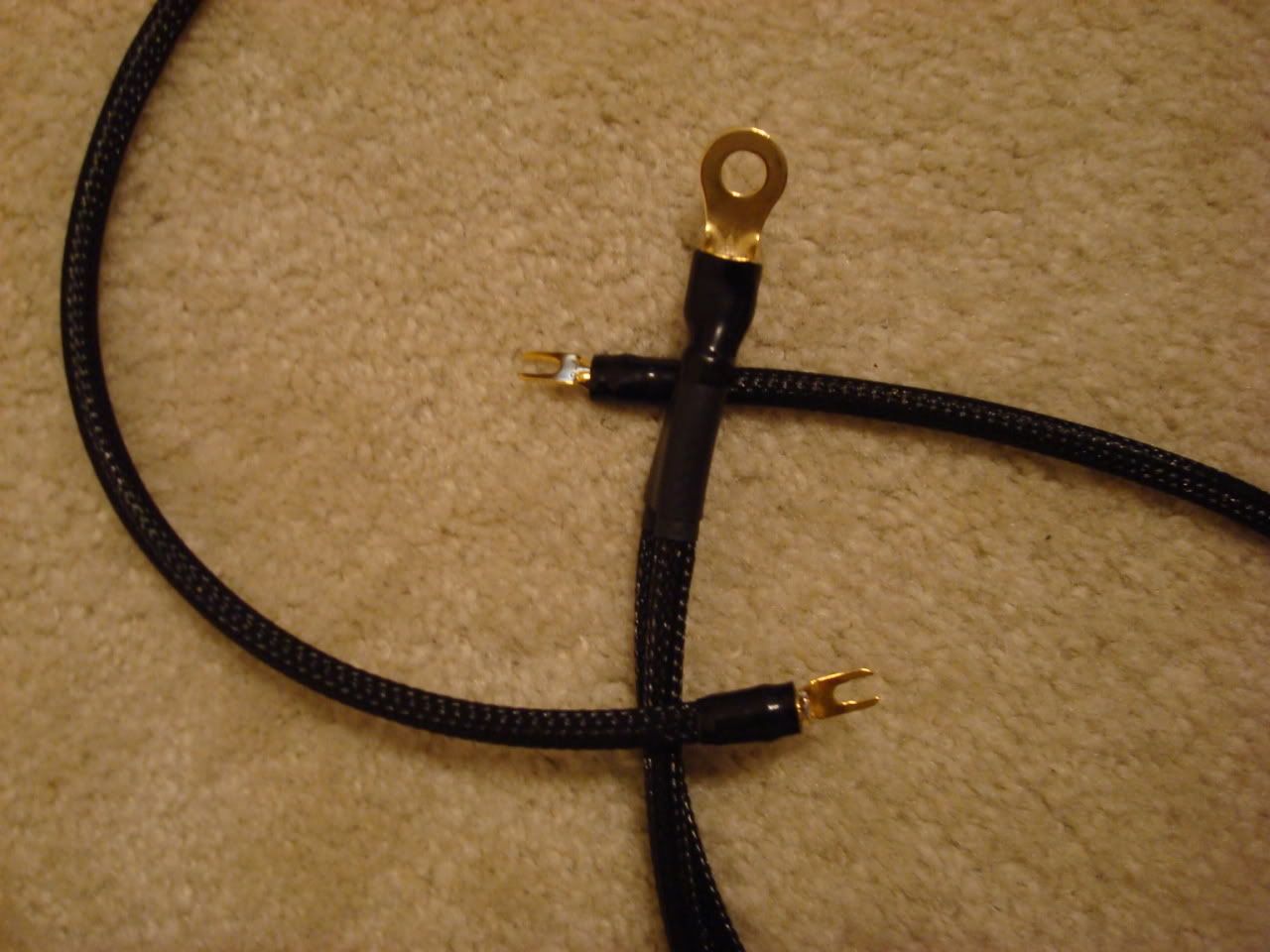
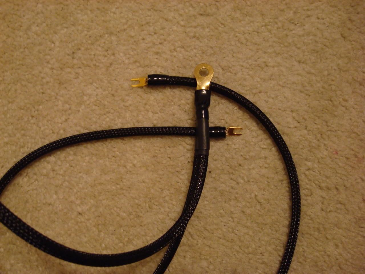
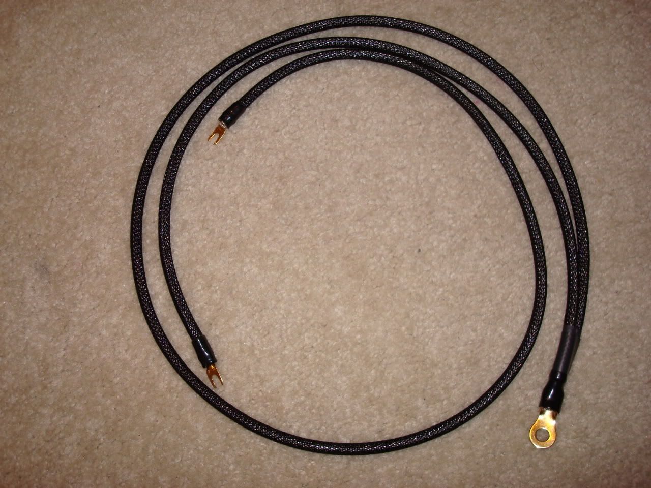
In addition to the instructions for the original wires, here's how to install the throttle body upgrade (the dual cable pictured above):
Remove your engine cover.
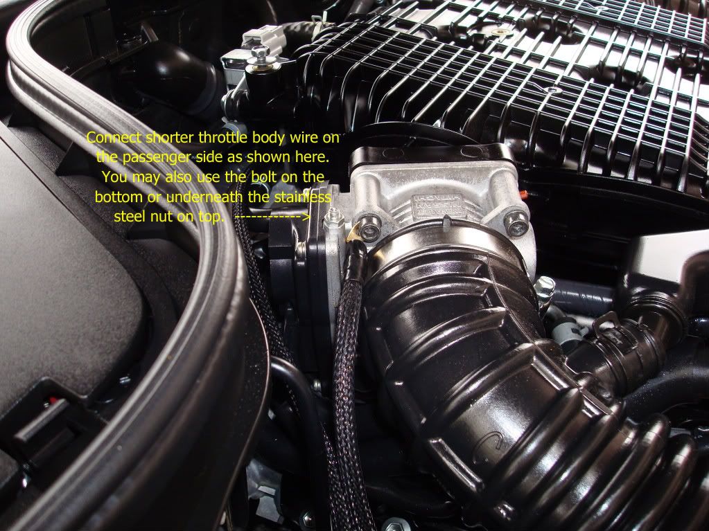
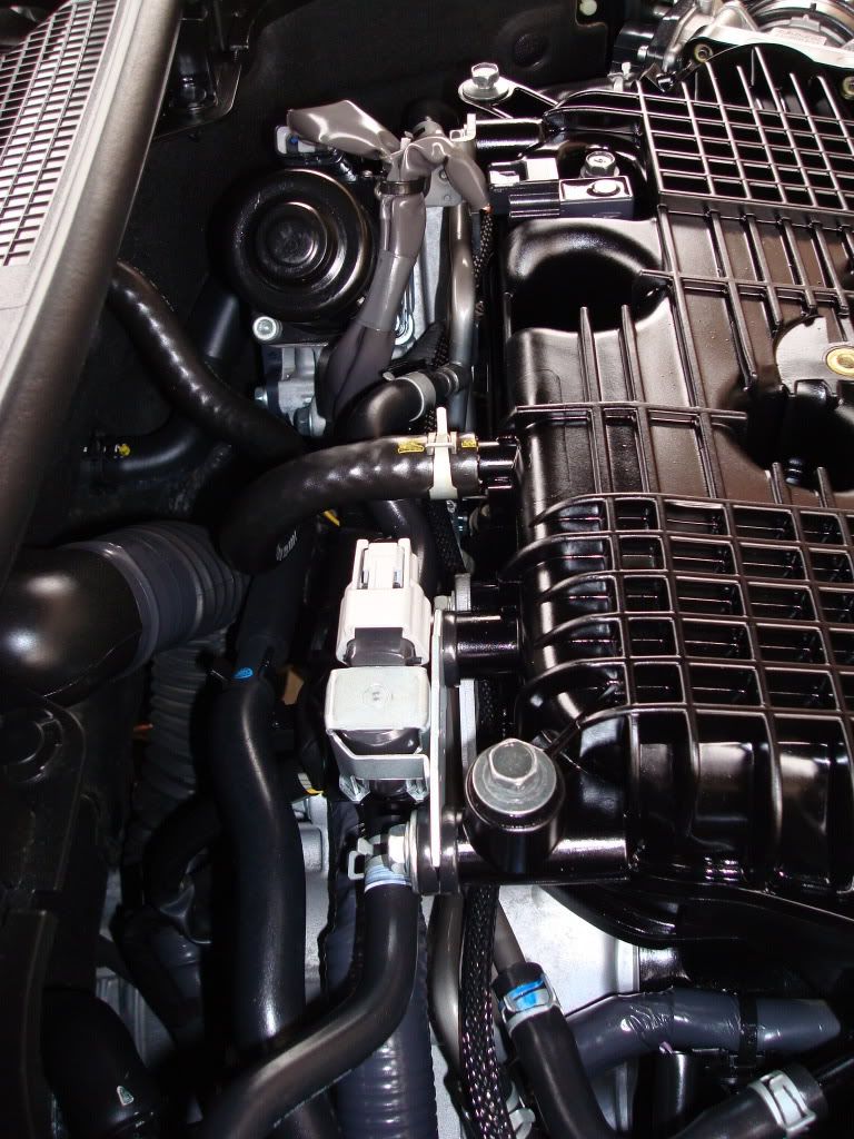
Connect the shorter of the two 8 AWG cables that have the spade terminal ends to the passenger side throttle body. You can do this in one of 3 places: 1) on the lower inset hex screw on the firewall side of the TB, 2) on the upper inset hex screw on the top firewall side of the TB, 3) underneath the stainless steel nut on top of the TB. The first 2 locations are a very tight fit and it may be easier to get the spade terminal connected by disconnecting the intake tubing. The spade will go on the TB screws but it's tight. The next larger size was too loose and may disconnect if you don't tighten the screw down enough. Under the nut on top of the TB is the easiest of the 3 locations (props to KODG MAN! ) but it's your choice as any of the three will work just fine.
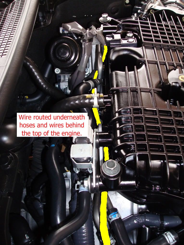
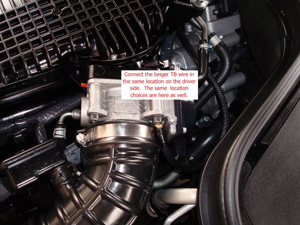
Connect the longer of the two 8 AWG cables that have the spade terminal ends to the driver side throttle body in your choice of the same 3 same locations as the other side. The cable length is designed to run underneath the various lines/hoses behind the top of the engine. This will make it very inconspicuous with the cover replaced and have it out of the way of everything.
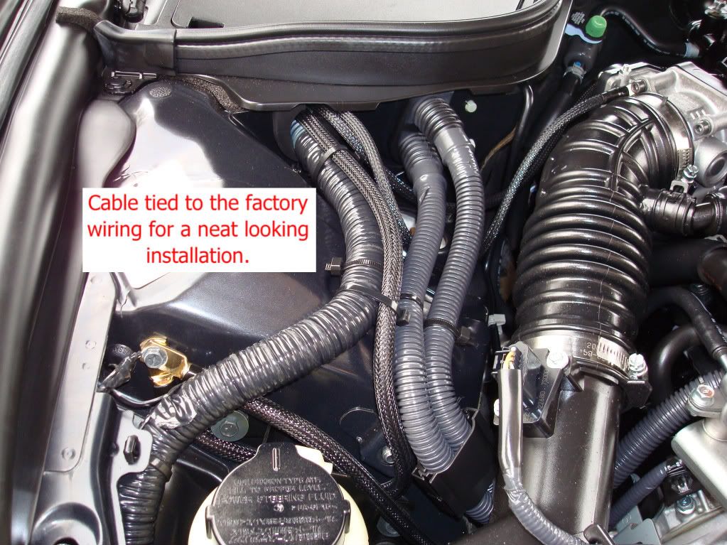
Finally, run the end with the 4 AWG ring terminal where both wires are spliced together back through the same grommet as the battery to chassis cable. Attach it alongside the other cable and reconnect your battery terminal.
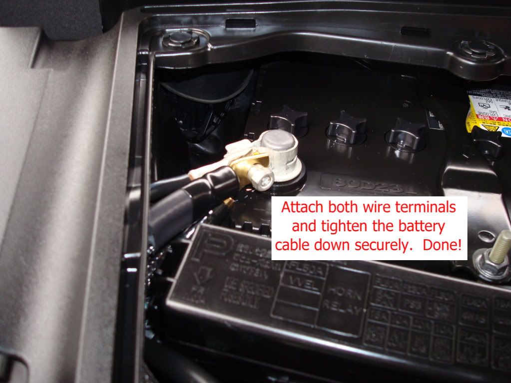
Done.
So here it is: Introducing Betty’s Garage grounding wire kits version 2.0.! In addition to the original wire set the new version now adds grounding for both throttle bodies. Why? Because directly grounding the throttle bodies improves throttle response of the drive by wire system in our G37s. It’s an 8 AWG cable from each TB merging to a single connector at the negative battery terminal. The TB ground wires are 8 AWG on both 4 and 8 AWG sets. 8 AWG is more than overkill, 16 gauge speaker wire would be sufficient but I made it 8 for continuity. The kits are still offered in the same colors: black, carbon fiber, red, blue, and white. Or you can order a custom color to be unique if you’re willing to wait a little longer for production.
The email address to reach me and to send PayPal payments is bettysgarage@earthlink.net. I am now able to ship same or next business day in most cases. USPS Priority Mail shipping is still the standard method but other methods including UPS are now available; if you prefer a different method be sure to let me know when placing your order.
When placing an order, be sure to send me a PM or email (bettysgarage@earthlink.net) with all the following information: your name, screen name, what color and size kit you'd like, what year and model G you have, and your shipping address if it is different from the one PayPal will give me.
Lastly thanks to all of you who’ve supported, bugged, encouraged, and inspired me in this endeavor. Your support means a lot to me.
In addition to the instructions for the original wires, here's how to install the throttle body upgrade (the dual cable pictured above):
Remove your engine cover.
Connect the shorter of the two 8 AWG cables that have the spade terminal ends to the passenger side throttle body. You can do this in one of 3 places: 1) on the lower inset hex screw on the firewall side of the TB, 2) on the upper inset hex screw on the top firewall side of the TB, 3) underneath the stainless steel nut on top of the TB. The first 2 locations are a very tight fit and it may be easier to get the spade terminal connected by disconnecting the intake tubing. The spade will go on the TB screws but it's tight. The next larger size was too loose and may disconnect if you don't tighten the screw down enough. Under the nut on top of the TB is the easiest of the 3 locations (props to KODG MAN!
) but it's your choice as any of the three will work just fine.Connect the longer of the two 8 AWG cables that have the spade terminal ends to the driver side throttle body in your choice of the same 3 same locations as the other side. The cable length is designed to run underneath the various lines/hoses behind the top of the engine. This will make it very inconspicuous with the cover replaced and have it out of the way of everything.
Finally, run the end with the 4 AWG ring terminal where both wires are spliced together back through the same grommet as the battery to chassis cable. Attach it alongside the other cable and reconnect your battery terminal.
Done.
Last edited by Black Betty; Aug 16, 2009 at 05:20 PM. Reason: Added instructions, photos
Do you think that you will notice a difference? BC I really only saw a slight difference with the grounding kit and I have the 5at...
Last edited by SOLISIMO; Dec 8, 2008 at 08:09 PM.

![]\[ /-\ ]\/['s Avatar](data:image/svg+xml;utf8,<svg xmlns='http://www.w3.org/2000/svg' viewBox='0 0 50 50'><circle class='avatar-circle-default' fill='%23de8a71' cx='25px' cy='25px' r='20px'></circle><text class='avatar-text-default' x='49%' y='53%' fill='white' text-anchor='middle' alignment-baseline='middle'>]</text></svg>)
No pics yet. Later this week.
I'll have as many at the meet as folks want to buy.


