
DIY GTM Turbo Stage 2 Install!!


DIY GTM Twin Turbo Stage 2 Install!!
Most of us have heard about this great turbo kit put together by GTM. Many shops have installed this kit on many G37s with great results. There are even a couple of people that have installed this kit as a DIY. However, I dont think anyone has detailed the installation process on the forums. I wanted to use this thread to journal my installation process as I install the kit in my backyard. 1. to kinda show that a turbo install isnt as complicated as people might think 2. to help anyone out if they want to go with my path.
Before anyone starts to make comments like how I should've let GTM install it, etc etc., let me say a few things. In addition to saving about 3 thousand dollars from the labor, installing this myself is 100 times more fun. I love to get my hands dirty and have always installed performance parts by myself. It always feel so damn good to finish a major project on your own. The car seems to gain more butt dyno WHP when you install parts on your own. Plus, its a great learning experience.
Before I start, I want to give special thanks to SAM@GTM for providing excellent parts for a great price. He offered me a before and after dyno, which I will post later.
Also special thanks to Tainui for giving me some really great advice and tips with my install. Tainui is one of the people that installed this kit DIY and has been really helpful to me. Thanks again!
Also wanted to thank TerryCS. In addition to providing the excellent screen protectors and remote covers, Terry answered a bunch of my PMs regarding his GTM turbo kit. Thanks again!
My setup:
-Stage 2 .86 A/R turbos
-Internal wastegates
-Powdercoated pipings
-Blitz sbc boost controller
-HKS 1 step colder spark plugs
To answer G37SAM's question, I consider myself to be pretty mechanically inclined. In my old G35, I've stripped the entire interior to dynamat and install a JL audio system. Installed small performance parts such as the spacers and mrev2 (G35 owners would know what i'm talking about ) In the end, a project like this just require you to have the right tools and a lot of patience.
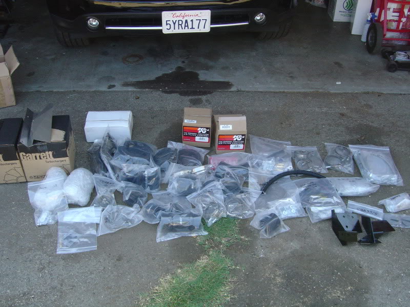
Alright on to the pictures:
Here is what the entire kit looks like. Notice how well they are packaged.
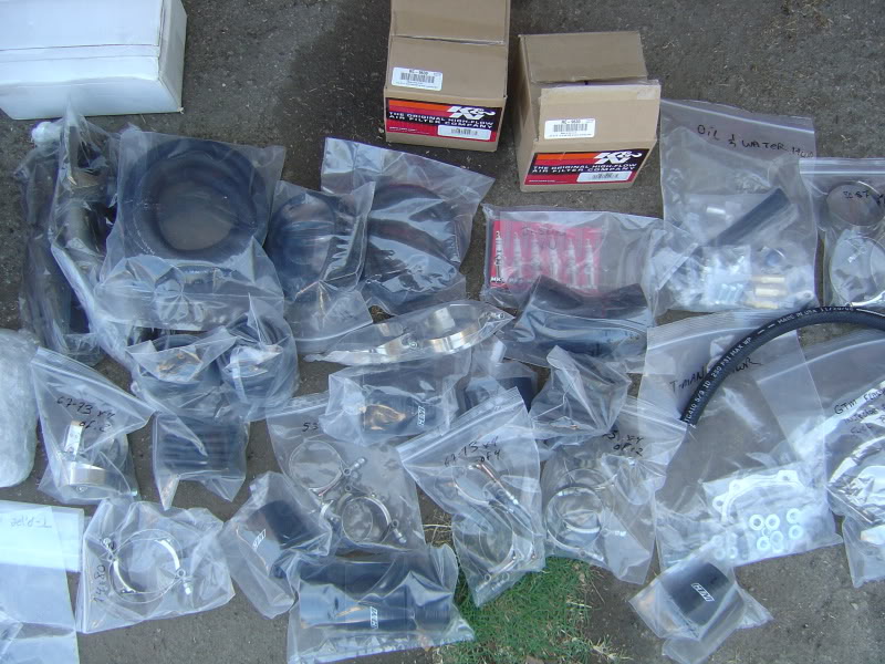
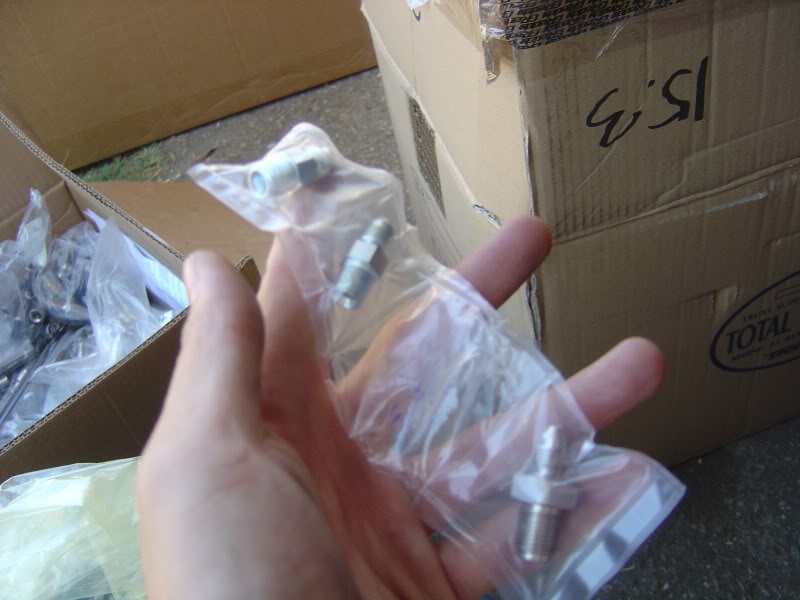
All the bolts, washers, wires, etc are bagged together depending on the component its for. For example, this bag is for the oil and water line parts.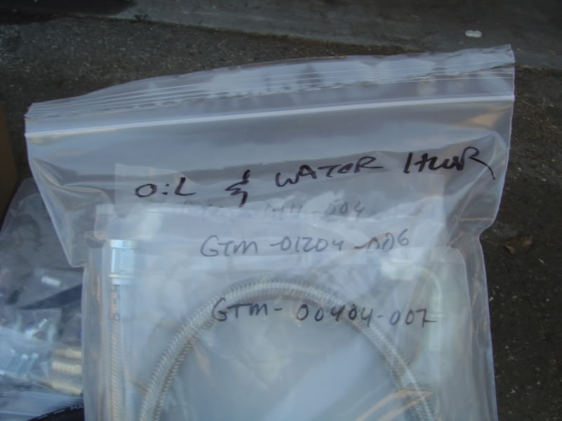
All the couplers and braces are labeled in the bags so its really easy to find what you need.
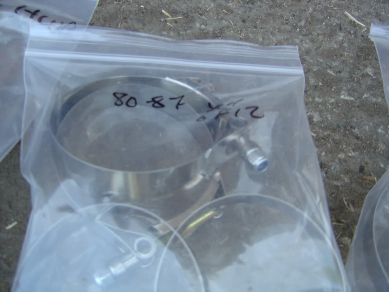
Check out how each tap is individually wrapped:
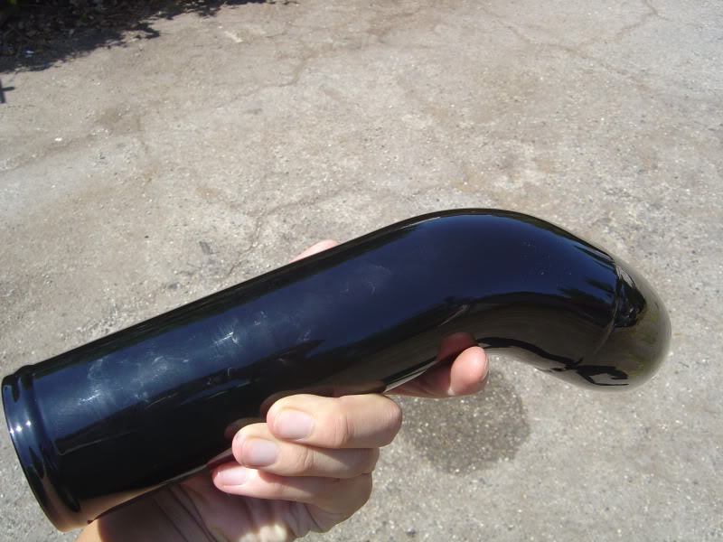
I went ahead and got the pipes powdercoated by GTM. I'm really happy with how the pipes look:
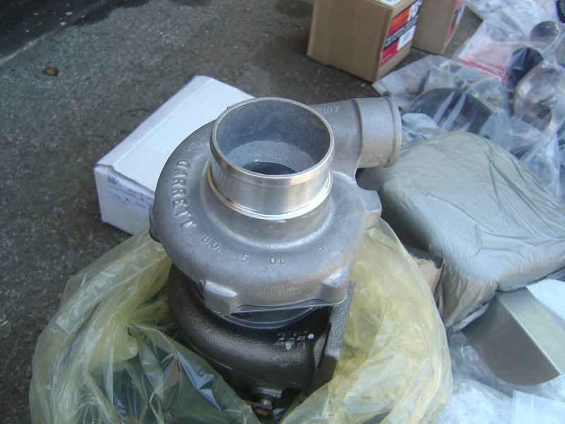
Stage 2 turbos:
So far I'm really happy with the completeness of the GTM kit. The way they packaged this kit will save me many hours of digging thru the boxes to find a bolt or nut. I'll keep updating this thread as I go thru the install each day.
Before anyone starts to make comments like how I should've let GTM install it, etc etc., let me say a few things. In addition to saving about 3 thousand dollars from the labor, installing this myself is 100 times more fun. I love to get my hands dirty and have always installed performance parts by myself. It always feel so damn good to finish a major project on your own. The car seems to gain more butt dyno WHP when you install parts on your own.
Plus, its a great learning experience. Before I start, I want to give special thanks to SAM@GTM for providing excellent parts for a great price. He offered me a before and after dyno, which I will post later.
Also special thanks to Tainui for giving me some really great advice and tips with my install. Tainui is one of the people that installed this kit DIY and has been really helpful to me. Thanks again!
Also wanted to thank TerryCS. In addition to providing the excellent screen protectors and remote covers, Terry answered a bunch of my PMs regarding his GTM turbo kit. Thanks again!
My setup:
-Stage 2 .86 A/R turbos
-Internal wastegates
-Powdercoated pipings
-Blitz sbc boost controller
-HKS 1 step colder spark plugs
To answer G37SAM's question, I consider myself to be pretty mechanically inclined. In my old G35, I've stripped the entire interior to dynamat and install a JL audio system. Installed small performance parts such as the spacers and mrev2 (G35 owners would know what i'm talking about
) In the end, a project like this just require you to have the right tools and a lot of patience. Alright on to the pictures:
Here is what the entire kit looks like. Notice how well they are packaged.
All the bolts, washers, wires, etc are bagged together depending on the component its for. For example, this bag is for the oil and water line parts.
All the couplers and braces are labeled in the bags so its really easy to find what you need.
Check out how each tap is individually wrapped:
I went ahead and got the pipes powdercoated by GTM. I'm really happy with how the pipes look:
Stage 2 turbos:
So far I'm really happy with the completeness of the GTM kit. The way they packaged this kit will save me many hours of digging thru the boxes to find a bolt or nut. I'll keep updating this thread as I go thru the install each day.
Last edited by Modme; Sep 21, 2009 at 11:36 AM.
Day 1:
I did my install a little different from the order that GTM suggested. First, I did everything that did not require the car to be lifted.
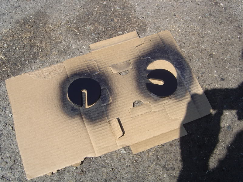
I started off by painting some of the metal parts prone to rust. As recommended by GTM, I painted the spacers, wastegate bracket, and steering linkage:
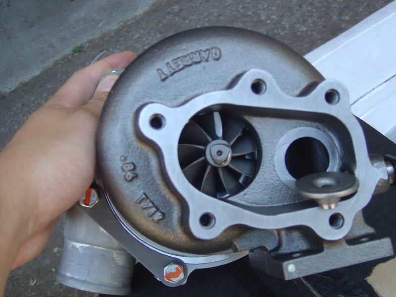
Then the turbos were prepped:
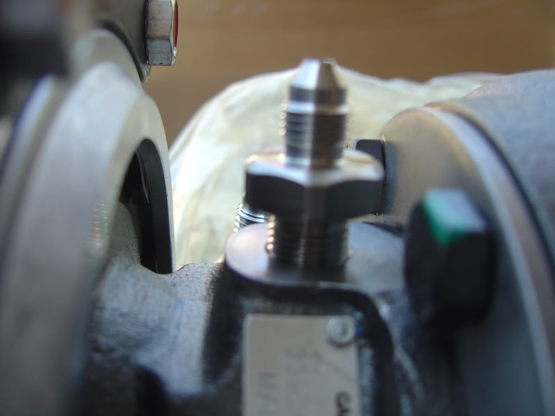
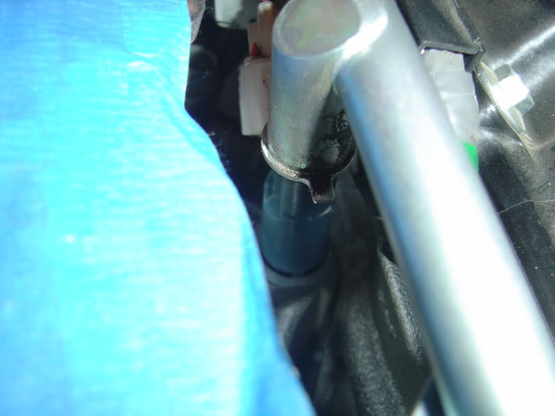
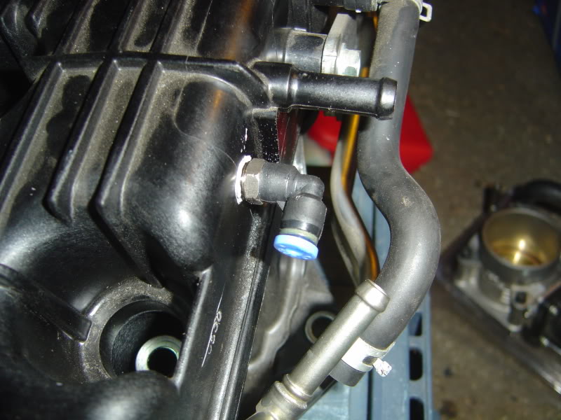
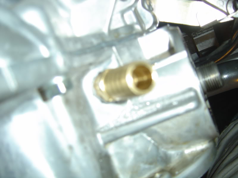
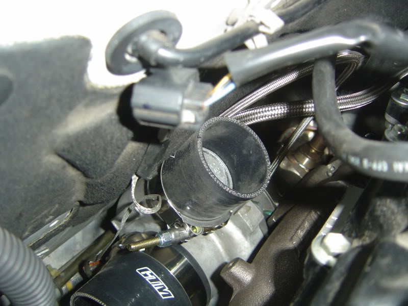
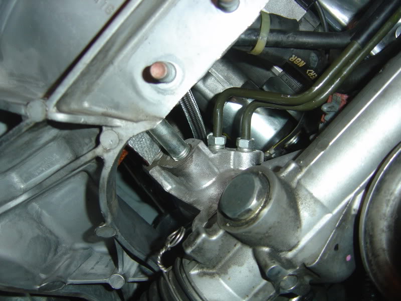
I wont go into all the details, it is outlined very well in the installation manual. But you need to loosen all the bolts on the turbo, lube it, and attach some of the drain and feed taps:
I do have a question about this tap on the passenger side turbo. Is the tap supposed to stick up like this? This is as far as it goes. Maybe Tainui or Sam can chime in?
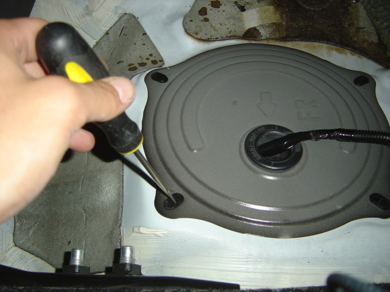
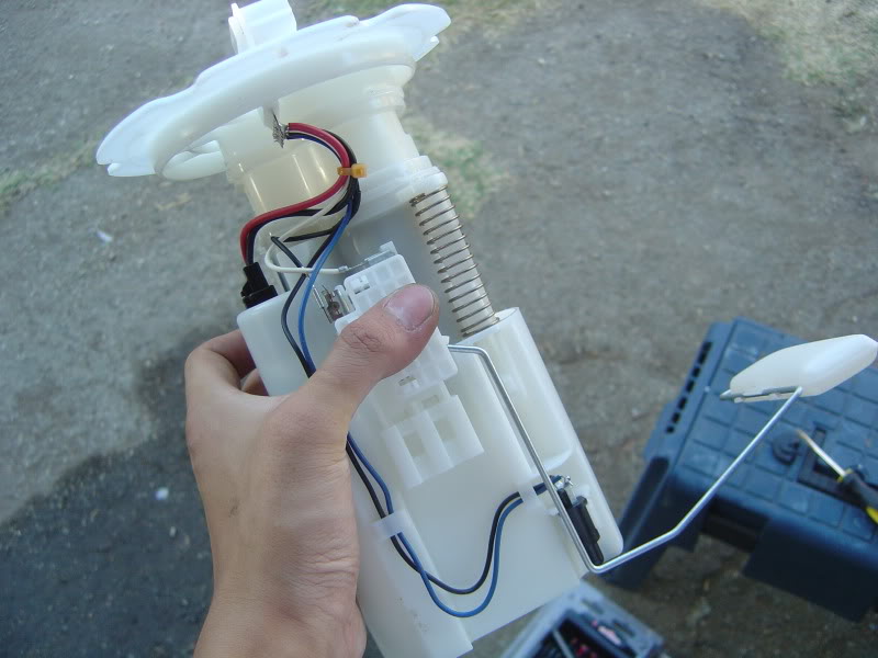
The stock fuel pump is taken out from the back seat. Just use a screw driver and twist the tabs:
Here is a picture of the stock pump next to the new walbro pump:
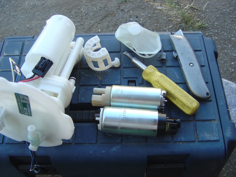
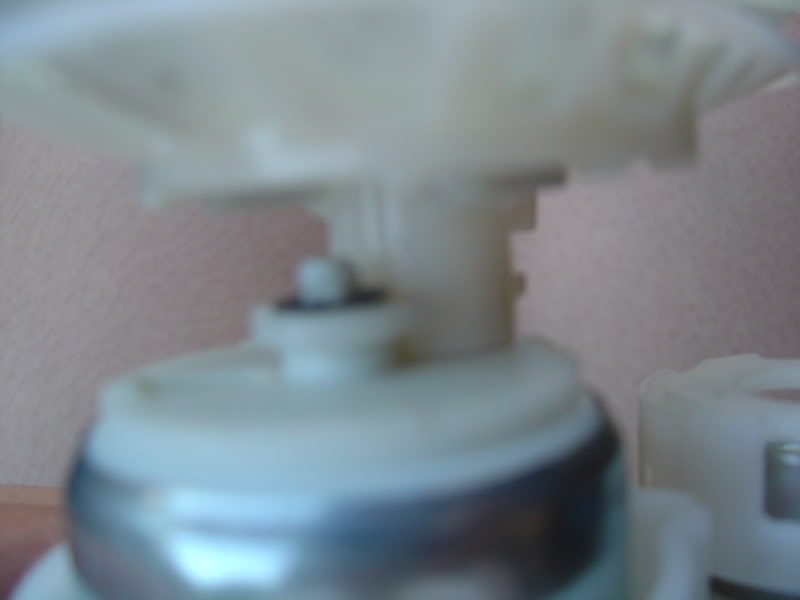
The walbro pump is longer than the stock one so the tabs on the bottom of the new pump have to be trimmed off to fit in the bucket.
Looks like this after tabs were removed:
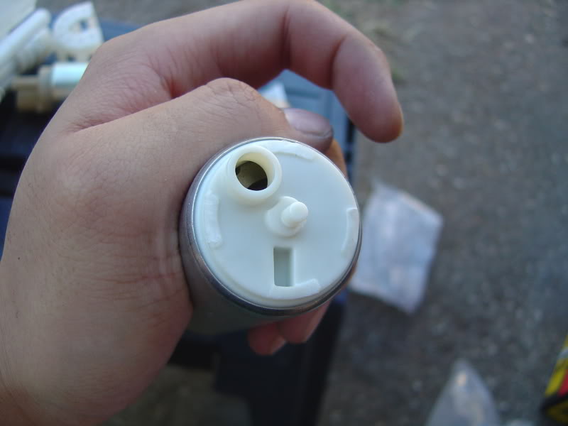
Take the fuel filter from the stock pump and replace it on the new one.
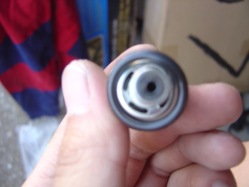
You need to drill the jet whirl using a 1/16" drill bit to enlarge the whole for the increased flow. Also need to drill the relief orifice using a 7/64" drill bit:
Put it all back together:
Time to tackle the engine bay to replace the injectors and spark plugs. Here is a picture of my current setup with injen CAI:
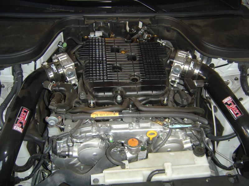
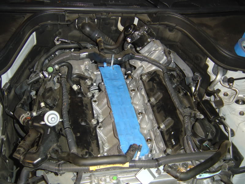
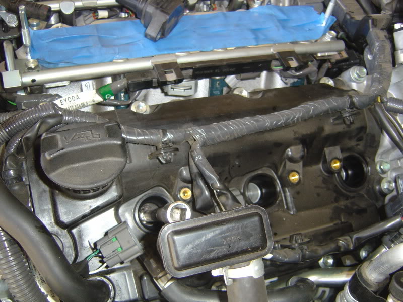
Nothing complicated here, just remove all the bolts holding the stock intake manifold and disconnect all the vacuum and water lines. Cover up the intake runners with painter's tape so no debris would enter the heads.
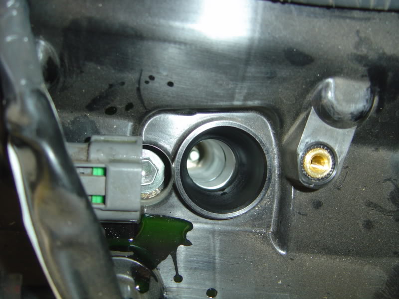
Remove the bolts for the fuel rails and pull the entire thing straight up. Make sure there is no orings stuck in the heads. Stock injectors look like this:
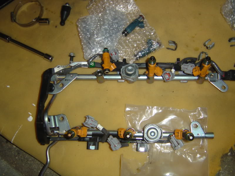
Unplug the harness and remove the clips. Then you can just pull the injectors out. Use the superlube that is provided with the kit and lube up the orings on the new 600cc injectors. Push the side with the brown orings into rails. There is no clips. Push in the stock harness. There is no cutting or soldering of wires.
600CC injectors installed:
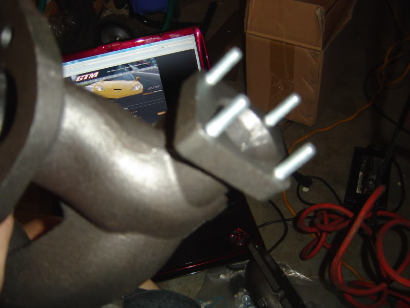
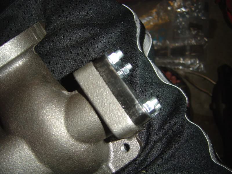
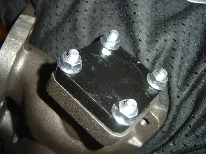
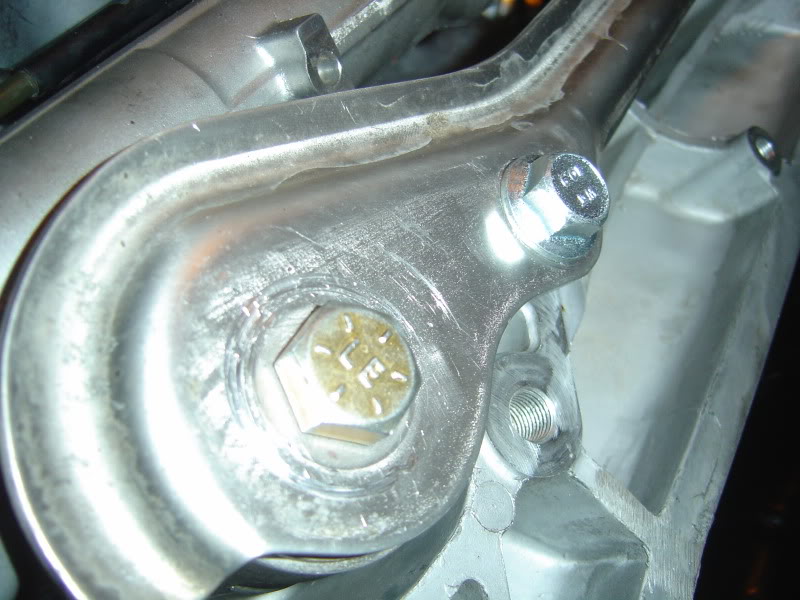
Then i went ahead and install the block off plate for the turbo manifold. This hole is usually for externally wastegated setups and the kit provides a block off plate for internally gated setups. I felt it would be easier to put in on now than after mounting it into the heads. You just simply put in the 4 provided studs, place the cover and tighten the nuts:
Do the same thing for the passenger side.
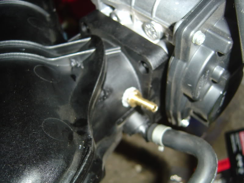
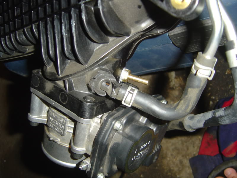
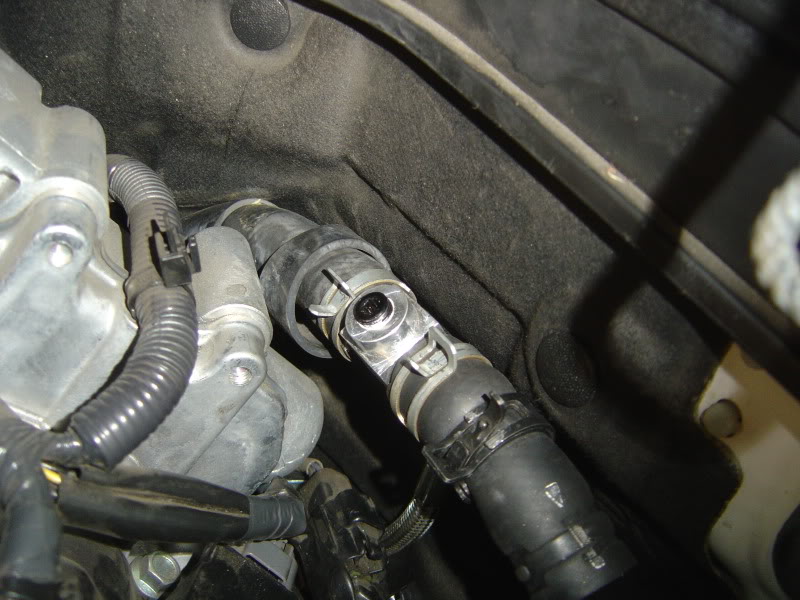
Now's a good time to tap the intake manifold for vacuum hoses. Just drill with a bit and tap with a 27 NPT tap. Apply some sealant and screw in the tap. Here is the driver side:
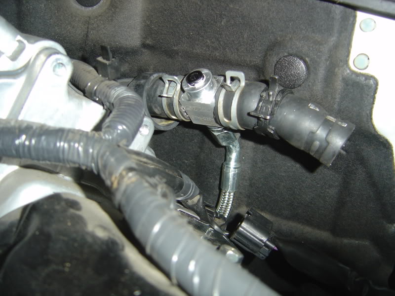
Passenger side:
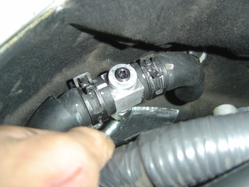
Rear tap:
Driver and passenger side taps are going to the blow off valves. The rear one will go to the MAP sensor on the boost controller.
That's all for now! Will update again after i finish working on it today.
I did my install a little different from the order that GTM suggested. First, I did everything that did not require the car to be lifted.
I started off by painting some of the metal parts prone to rust. As recommended by GTM, I painted the spacers, wastegate bracket, and steering linkage:
Then the turbos were prepped:
I wont go into all the details, it is outlined very well in the installation manual. But you need to loosen all the bolts on the turbo, lube it, and attach some of the drain and feed taps:
I do have a question about this tap on the passenger side turbo. Is the tap supposed to stick up like this? This is as far as it goes. Maybe Tainui or Sam can chime in?
The stock fuel pump is taken out from the back seat. Just use a screw driver and twist the tabs:
Here is a picture of the stock pump next to the new walbro pump:
The walbro pump is longer than the stock one so the tabs on the bottom of the new pump have to be trimmed off to fit in the bucket.
Looks like this after tabs were removed:
Take the fuel filter from the stock pump and replace it on the new one.
You need to drill the jet whirl using a 1/16" drill bit to enlarge the whole for the increased flow. Also need to drill the relief orifice using a 7/64" drill bit:
Put it all back together:
Time to tackle the engine bay to replace the injectors and spark plugs. Here is a picture of my current setup with injen CAI:
Nothing complicated here, just remove all the bolts holding the stock intake manifold and disconnect all the vacuum and water lines. Cover up the intake runners with painter's tape so no debris would enter the heads.
Remove the bolts for the fuel rails and pull the entire thing straight up. Make sure there is no orings stuck in the heads. Stock injectors look like this:
Unplug the harness and remove the clips. Then you can just pull the injectors out. Use the superlube that is provided with the kit and lube up the orings on the new 600cc injectors. Push the side with the brown orings into rails. There is no clips. Push in the stock harness. There is no cutting or soldering of wires.
600CC injectors installed:
Then i went ahead and install the block off plate for the turbo manifold. This hole is usually for externally wastegated setups and the kit provides a block off plate for internally gated setups. I felt it would be easier to put in on now than after mounting it into the heads. You just simply put in the 4 provided studs, place the cover and tighten the nuts:
Do the same thing for the passenger side.
Now's a good time to tap the intake manifold for vacuum hoses. Just drill with a bit and tap with a 27 NPT tap. Apply some sealant and screw in the tap. Here is the driver side:
Passenger side:
Rear tap:
Driver and passenger side taps are going to the blow off valves. The rear one will go to the MAP sensor on the boost controller.
That's all for now! Will update again after i finish working on it today.
Last edited by Modme; Sep 21, 2009 at 11:26 AM.
Day 2:
Today was a slow install day. I found out what others meant when they say headers are hard to remove. Anyways, I started off installing the new HKS spark plugs. With the intake manifold off, the install was a cinch. The spark plugs are 14mm and you'll need an extension to reach down to them. Just swap them out and torque them down to factory spec.
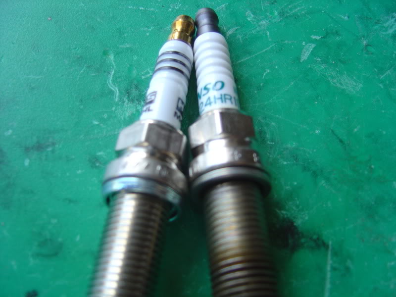
Here is a side by side view of stock and HKS sparks.
Now onto the headers.
The passenger side was not too bad. The heat shield came out pretty easily after removing 3 bolts. Then I removed the oxygen sensor from underneath the car. I had them soaked in PB Blaster overnight, so they came out very easily and cleanly. There are 6 bolts holding the header in, 3 on top and 3 on bottom. Using different ratchet bits and extensions, I go all of the bolts out. There is plenty of room to work with. Let the header fall down thru the bottom.
The driver side header is a major PITA. There is hardly any room to work with. The hardest part for me was actually getting the heat shield out. The bolts can be removed easily but there is not enough gap for the shield to be pulled out. It took me an hour just rotating and banging on the shield to finally get it out. The rest is not too bad. Again using different bits and extensions, slowly remove the six bolts and let the header come out from the bottom.
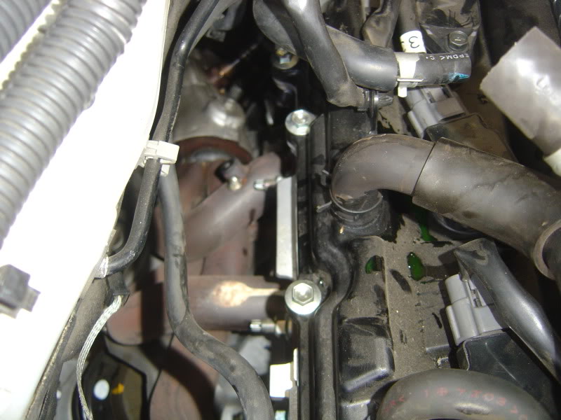
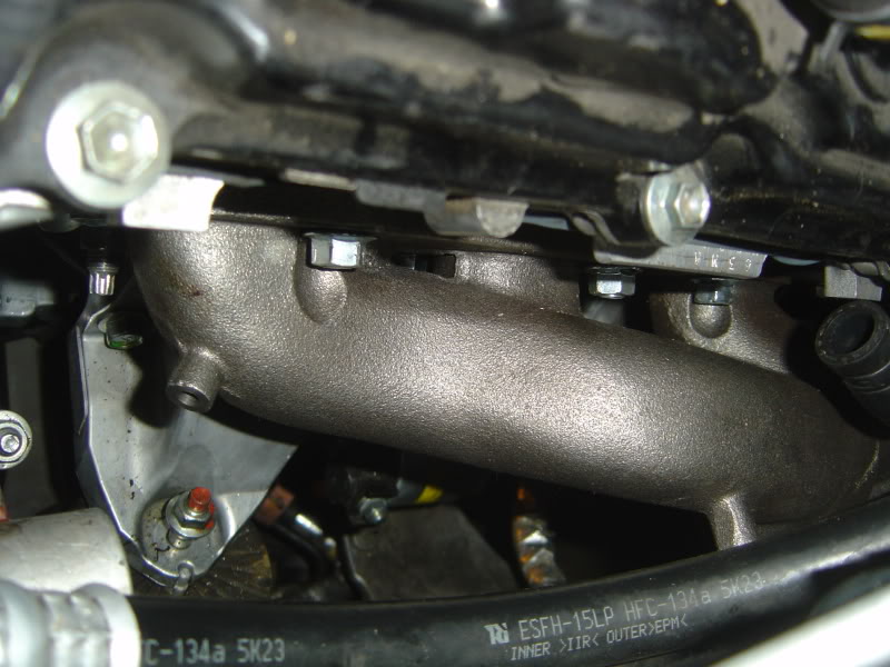
Here is a picture of passenger side with the header removed.
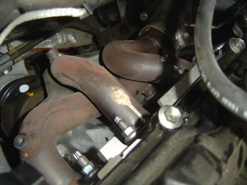
In order to fit the new turbo manifold, 2 of the studs have to be removed from the passenger side. You use 4 nuts to bolt down the front of the header and 2 allen bolts to fasten the rear. The two allen bolts screws into a different location than the stock stud.
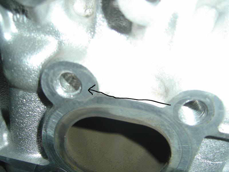
As I found out, the new location is not threaded and you have to tap it yourself. You need a 10m x 1.25 tap.
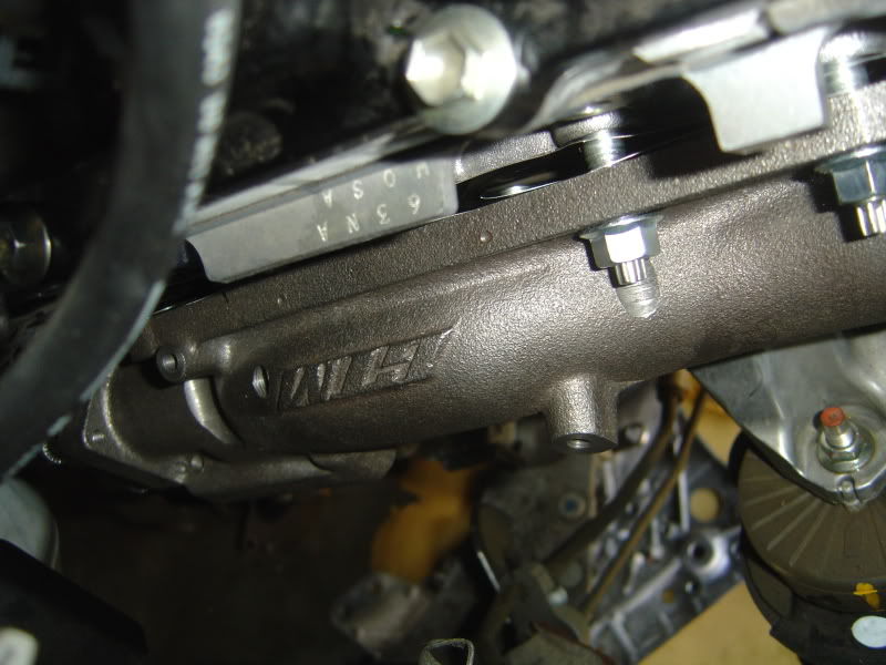
Finally, I was able fasten the passenger turbo manifold.
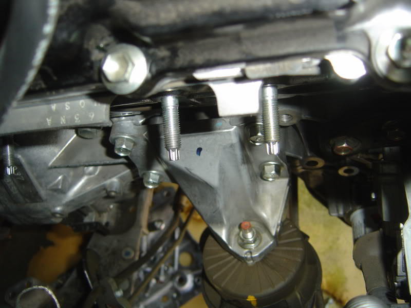
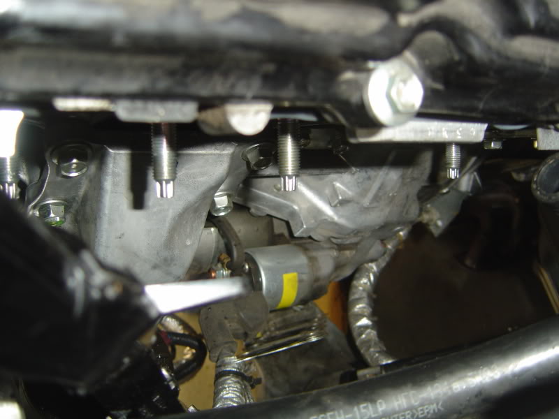
Here is a picture of the driver side with the header removed. I have no attached the manifold yet. Will tackle that tomorrow.
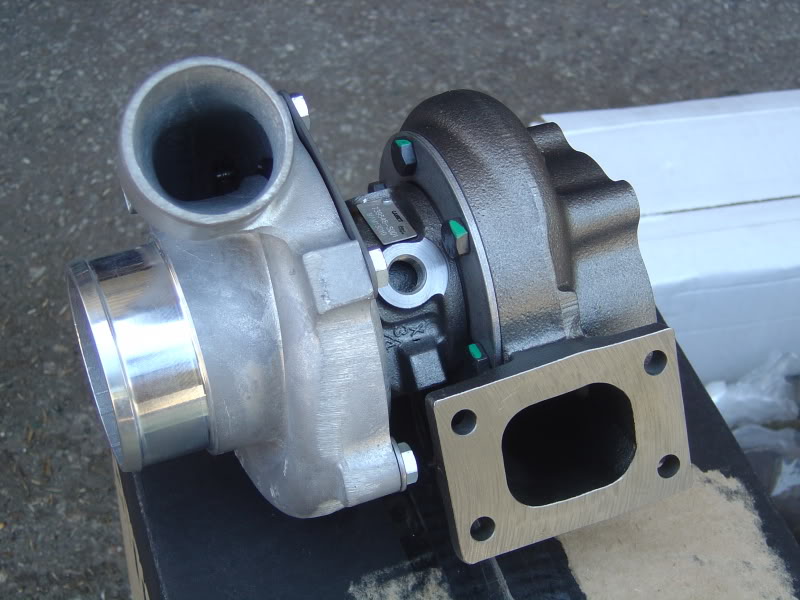
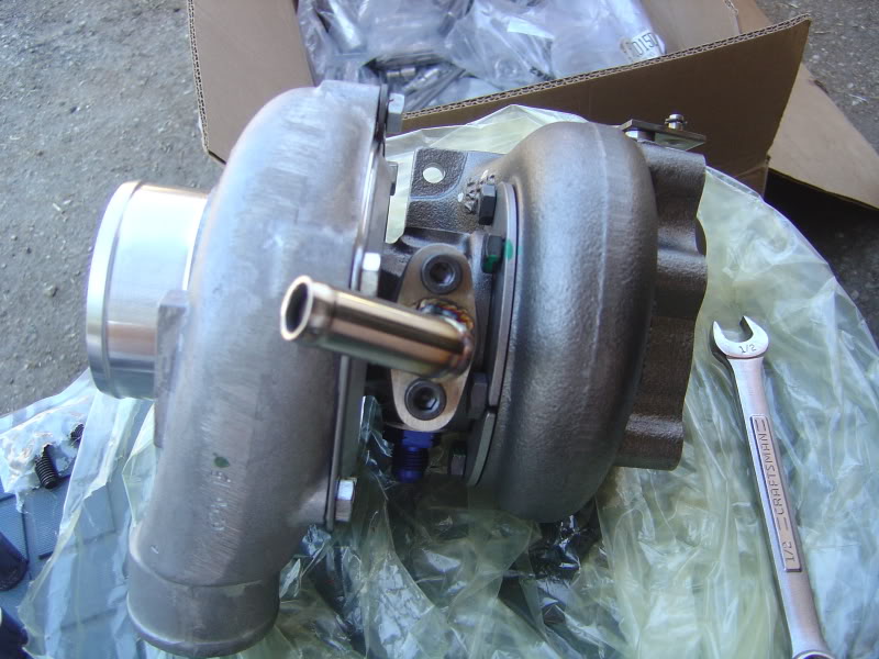
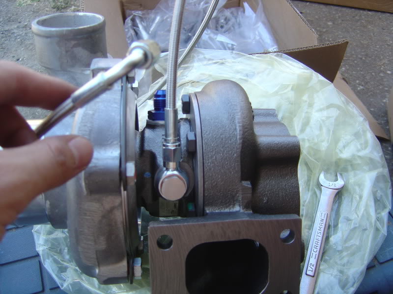
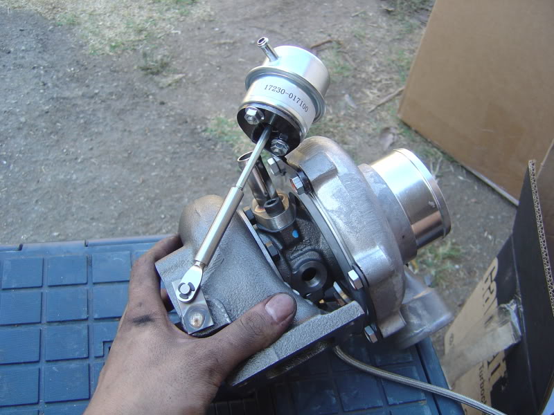
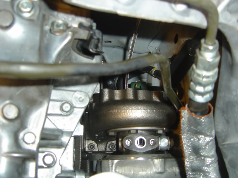
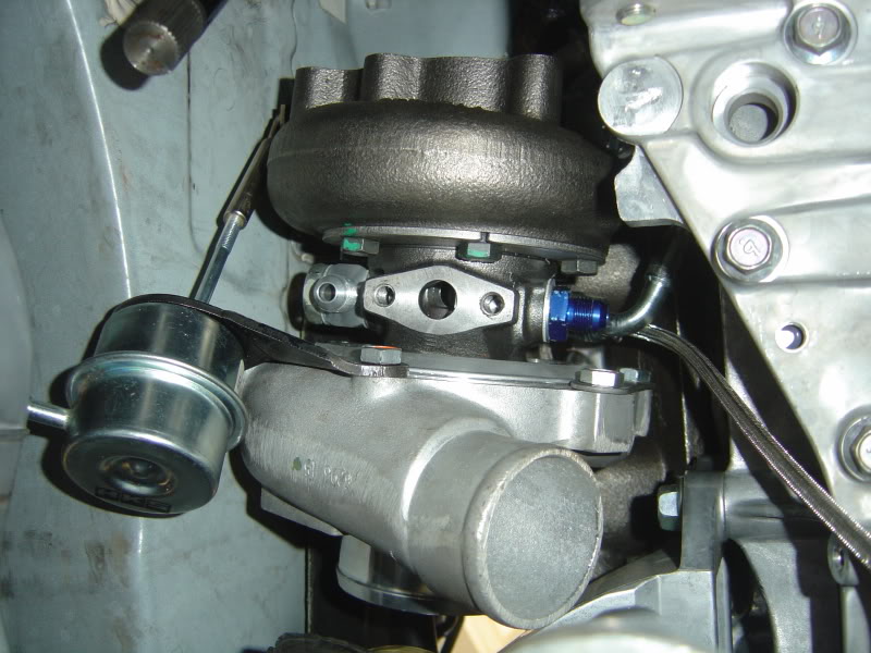
And here is a picture of the turbo fully assembled with the internal wastegates:
Day 3-4
Update:
I have not really been able to work on install during the weekdays. I only have about 2-3 hours every night after work to do some small things. In the last couple of days I was able to get the driver side turbo manifold mounted and oil return fittings tapped.
Driver side manifold install was another major PITA. First of all, you need to relocate 2 studs, which mean you need to tap another 2 threads. The top row studs need to be taken out and replaced with shorter studs. But those are the easy parts. The gap between the engine and fender wall is tiny and the manifold is big. Even with the small studs, the manifold still has trouble fitting into the studs and the side rubs against the fender wall foam. So I had to use a rubber mallet and help convince the manifold to go in the studs. After it goes fully into the studs, the side no longer rubs against the fender wall. The nuts are also harder to tighten because of the lack of space. But after 5 cuts or so on my hands, the manifold is mounted. Make sure you don�t forget to put in the gasket first. You don�t want to have to mount it twice.
The oil pan tap was much easier than I expected. However, you need to have the right parts before starting. We need to tap 2 holes for the oil drain. The size of the thread is brass fitting 3/8 NPT. This was a very hard tap size to locate. For some reason, brass fitting sizes are different from normal fittings. Even though it says its 3/8�, the fitting is actually around 5/8�. I was finally able to locate this part at Harbor Freight Tools. You also need an angled drill. The pan is small so you won�t be able to fit a regular drill.
First of all, you need to drill a small hole and increase the size until 37/64� drill bit. However, the biggest drill bit I had was a 1/2�. So I used a dremel to enlarge the hole slightly. Be careful when you do this. If you make the hole too big, the fitting might fit loosely and you�ll have a leak.
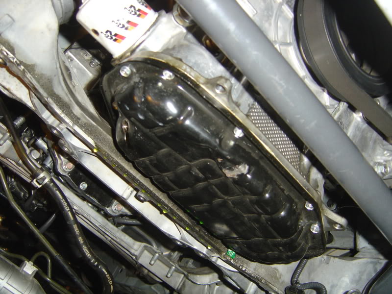
Splitting the pan is fairly simple. Use a 10mm ratchet and remove all the bolts. Then use a small thin flat head screw driver and separate the pan. It should look something like this:
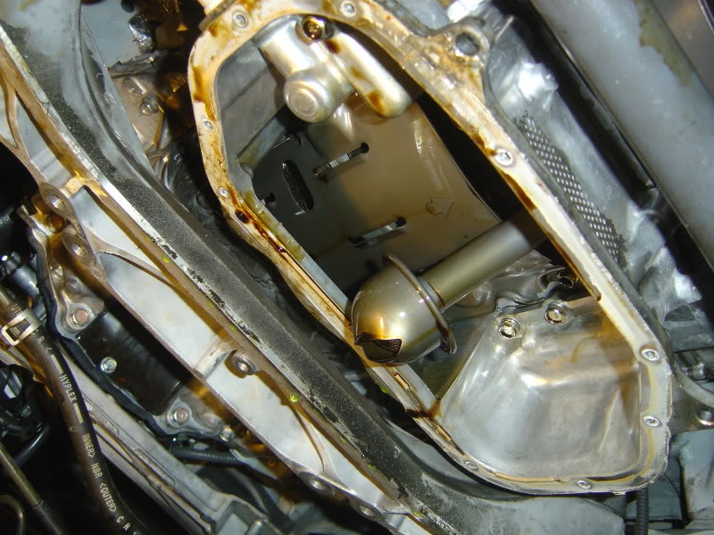
Then you need to remove the oil funnel thing by removing 2 x 12mm bolts. Then you can mark your location and start drilling with a small drill bit first and then enlarge it. It should look something like this:
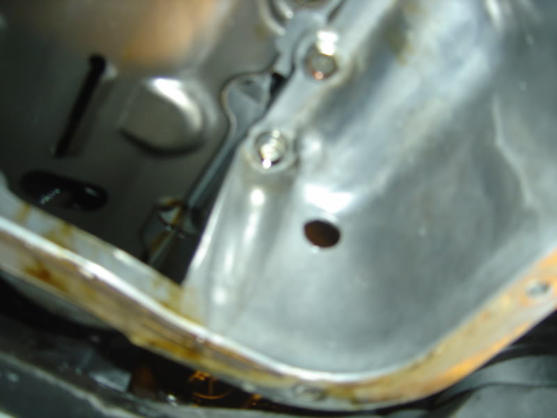
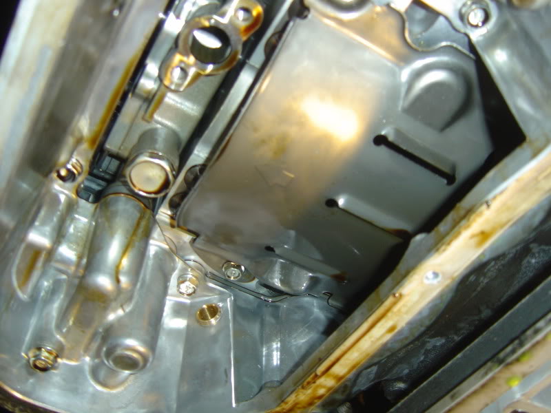
Make sure you tap the thread from the outside in because you want the fitting to fit from the outside. Here are pictures of the driver side installed:
Then just clean off all the metal debris, reinstall the oil funnel thing, add gasket to the oil pan and bolt it shut.
That�s all for now!
Today was a slow install day. I found out what others meant when they say headers are hard to remove. Anyways, I started off installing the new HKS spark plugs. With the intake manifold off, the install was a cinch. The spark plugs are 14mm and you'll need an extension to reach down to them. Just swap them out and torque them down to factory spec.
Here is a side by side view of stock and HKS sparks.
Now onto the headers.
The passenger side was not too bad. The heat shield came out pretty easily after removing 3 bolts. Then I removed the oxygen sensor from underneath the car. I had them soaked in PB Blaster overnight, so they came out very easily and cleanly. There are 6 bolts holding the header in, 3 on top and 3 on bottom. Using different ratchet bits and extensions, I go all of the bolts out. There is plenty of room to work with. Let the header fall down thru the bottom.
The driver side header is a major PITA. There is hardly any room to work with. The hardest part for me was actually getting the heat shield out. The bolts can be removed easily but there is not enough gap for the shield to be pulled out. It took me an hour just rotating and banging on the shield to finally get it out. The rest is not too bad. Again using different bits and extensions, slowly remove the six bolts and let the header come out from the bottom.
Here is a picture of passenger side with the header removed.
In order to fit the new turbo manifold, 2 of the studs have to be removed from the passenger side. You use 4 nuts to bolt down the front of the header and 2 allen bolts to fasten the rear. The two allen bolts screws into a different location than the stock stud.
As I found out, the new location is not threaded and you have to tap it yourself. You need a 10m x 1.25 tap.
Finally, I was able fasten the passenger turbo manifold.
Here is a picture of the driver side with the header removed. I have no attached the manifold yet. Will tackle that tomorrow.
And here is a picture of the turbo fully assembled with the internal wastegates:
Day 3-4
Update:
I have not really been able to work on install during the weekdays. I only have about 2-3 hours every night after work to do some small things. In the last couple of days I was able to get the driver side turbo manifold mounted and oil return fittings tapped.
Driver side manifold install was another major PITA. First of all, you need to relocate 2 studs, which mean you need to tap another 2 threads. The top row studs need to be taken out and replaced with shorter studs. But those are the easy parts. The gap between the engine and fender wall is tiny and the manifold is big. Even with the small studs, the manifold still has trouble fitting into the studs and the side rubs against the fender wall foam. So I had to use a rubber mallet and help convince the manifold to go in the studs. After it goes fully into the studs, the side no longer rubs against the fender wall. The nuts are also harder to tighten because of the lack of space. But after 5 cuts or so on my hands, the manifold is mounted. Make sure you don�t forget to put in the gasket first. You don�t want to have to mount it twice.
The oil pan tap was much easier than I expected. However, you need to have the right parts before starting. We need to tap 2 holes for the oil drain. The size of the thread is brass fitting 3/8 NPT. This was a very hard tap size to locate. For some reason, brass fitting sizes are different from normal fittings. Even though it says its 3/8�, the fitting is actually around 5/8�. I was finally able to locate this part at Harbor Freight Tools. You also need an angled drill. The pan is small so you won�t be able to fit a regular drill.
First of all, you need to drill a small hole and increase the size until 37/64� drill bit. However, the biggest drill bit I had was a 1/2�. So I used a dremel to enlarge the hole slightly. Be careful when you do this. If you make the hole too big, the fitting might fit loosely and you�ll have a leak.
Splitting the pan is fairly simple. Use a 10mm ratchet and remove all the bolts. Then use a small thin flat head screw driver and separate the pan. It should look something like this:
Then you need to remove the oil funnel thing by removing 2 x 12mm bolts. Then you can mark your location and start drilling with a small drill bit first and then enlarge it. It should look something like this:
Make sure you tap the thread from the outside in because you want the fitting to fit from the outside. Here are pictures of the driver side installed:
Then just clean off all the metal debris, reinstall the oil funnel thing, add gasket to the oil pan and bolt it shut.
That�s all for now!
Last edited by Modme; Sep 24, 2009 at 03:04 PM.
Day 4, 5, 6:
Sorry for the late update everyone. I’ve been working hard on the install all weekend and did not have a chance to update the thread.
Mounting the turbo: The installation manual tells you to prepare the turbo by attaching the oil return drain and mounting the wastegate actuator. Don’t do it. If you leave the oil drain and actuator off, the mounting process is 100 times easier. It’s very easy to install those things after mounting the turbo anyways. Also, I would suggest that you install the engine mount spacers before attaching the turbos. It will give you more room to work with. You do not need to remove the clutch lines to install the driver side turbo but you need to take off the starter.
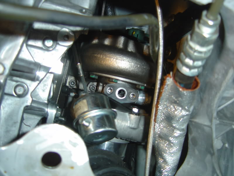
To mount the turbo, you need to add two studs to the rear side of the turbo manifold, place the gasket, and then attach the turbo. Orient everything as pictured. For the passenger side, you want the air intake side to face towards front of the car and the charge air pipe to face up towards the hood. For driver side, you need the intake side to face forward and the charge air pipe to face downward. You need to orient both turbos to have the drain tap face downward. Secure the two turbos with two nuts in the rear and two allen head bolts in the front.
Passenger side:
After mounting the turbo and orienting everything, you need to tighten all the brackets that secure the turbo housing. There are 6 bolts for the hot side and 6 for the cold side. Some of the bolts will be tricky to get to. Use crow’s foot attachments to help you secure the bolts. Leave the 2 bolts for the wastegate actuator on the cold side.
Then you need to add the coolant fitting:
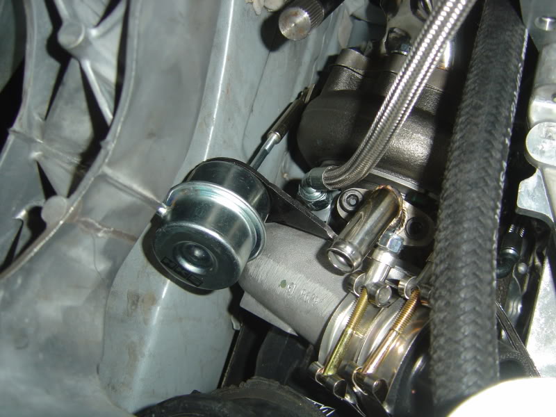
Then you mount the wastegate actuator. This is a very important step and is a little tricky. You have to make sure the wastegate is just fully closed normally. You can adjust this by twisting the arm bracket on the actuator. Notice I had to bend the tip of the arm at a small angle to make sure the valve opens smoothly. Then tighten the bracket onto the turbo housing.
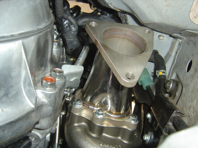
Now you can mount the oil drain. After that attach the exhaust manifold:
Do the same thing for the driver side.
Running water lines:
There are three different water lines. One line goes from driver side heater hose to turbo. Second line goes from turbo to turbo, and third line goes from passenger turbo to passenger heater hose.
Turbo heatshield:
These are very easy to install. Just move them around to get them to fit.
After attaching the heatshield on the driver side, you can reinstall the coolant piping:
Remounting the starter:
First you need to straight up the wire terminal that bolts to the starter. You have play around with the bracket and make it mount sideways as seen here:
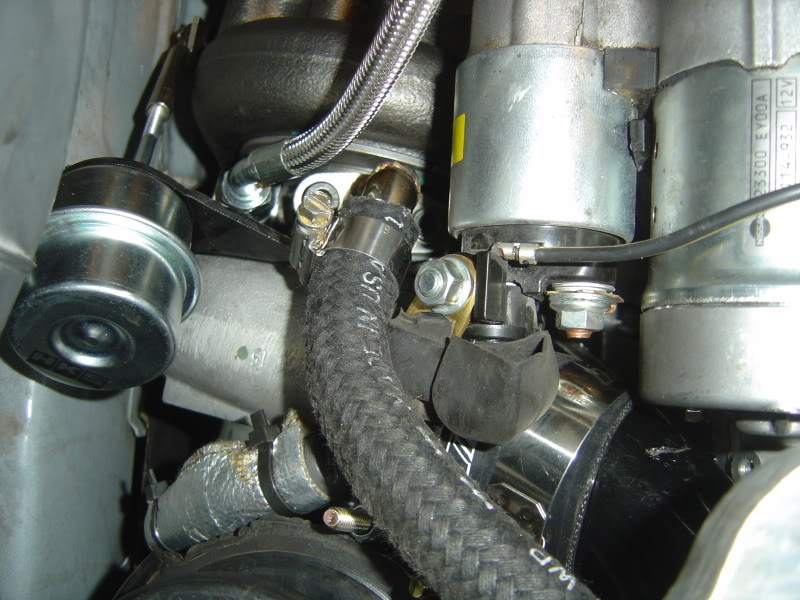
You can also see the oil drain tubing.
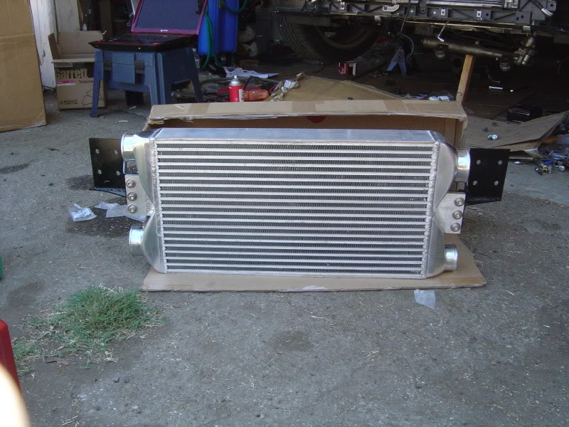
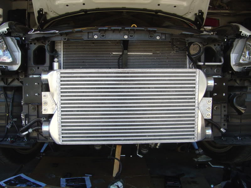
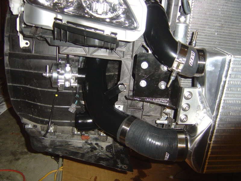
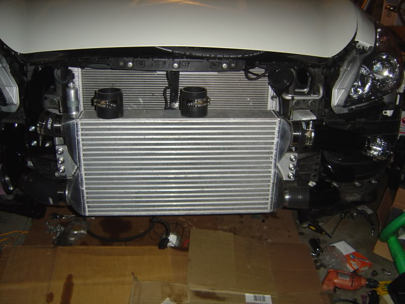
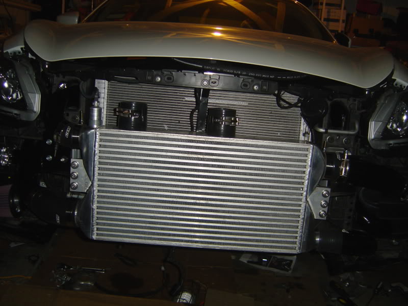
Mounting the intercooler:
This is probably the easiest step. First line up the bracket correctly. Attach brackets to the intercooler but keep them loose. Then just attach to the car.
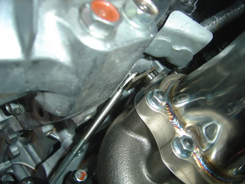
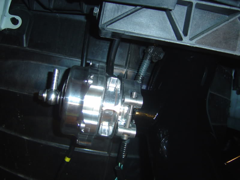
Remounting the steering column:
Push everything back in and use the provided spacers and longer bolt to mount the column. This makes sure that the steering column does not hit the turbo housing:
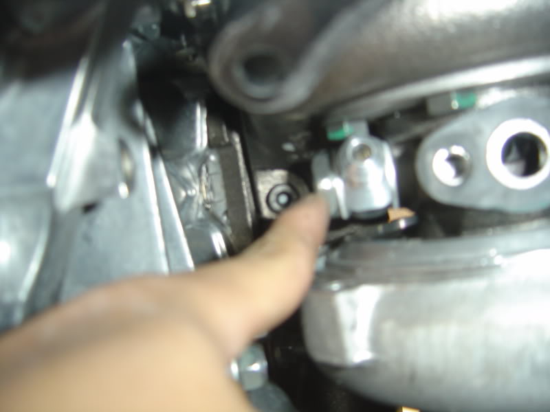
I did run into a problem while mounting the steering knuckle.
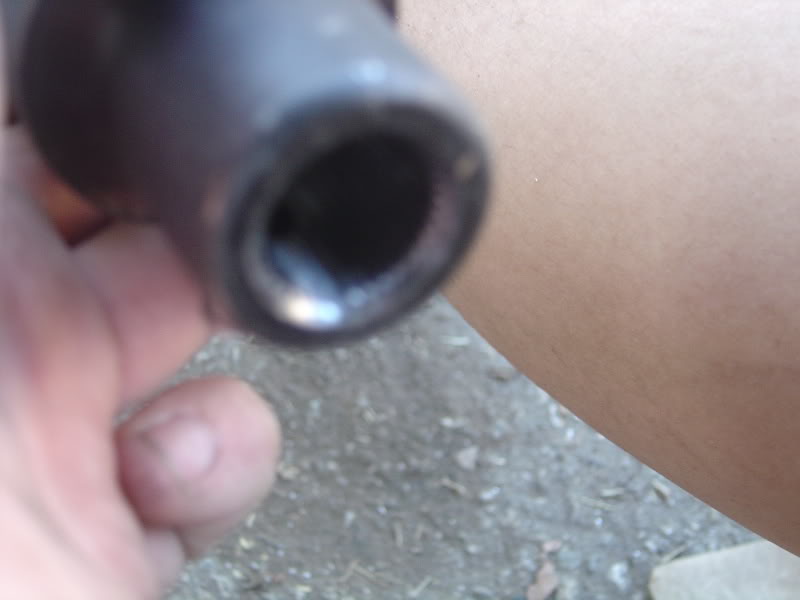
The factory steering rod has 2 alignment groves like this:
However, the GTM knuckle only had 1 grove so it wouldn’t go in the steering rod. I had to drill another alignment grove to make it fit. Assemble the knuckle like this:
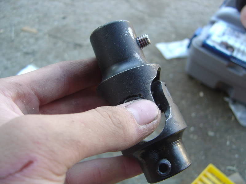
The longer portion goes into the steering rod and the shorter section goes into the blue steering column.
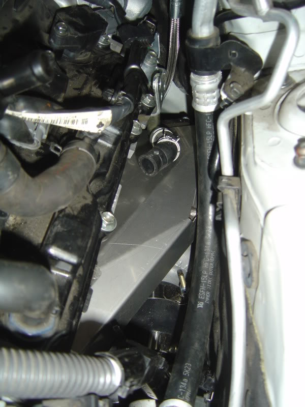
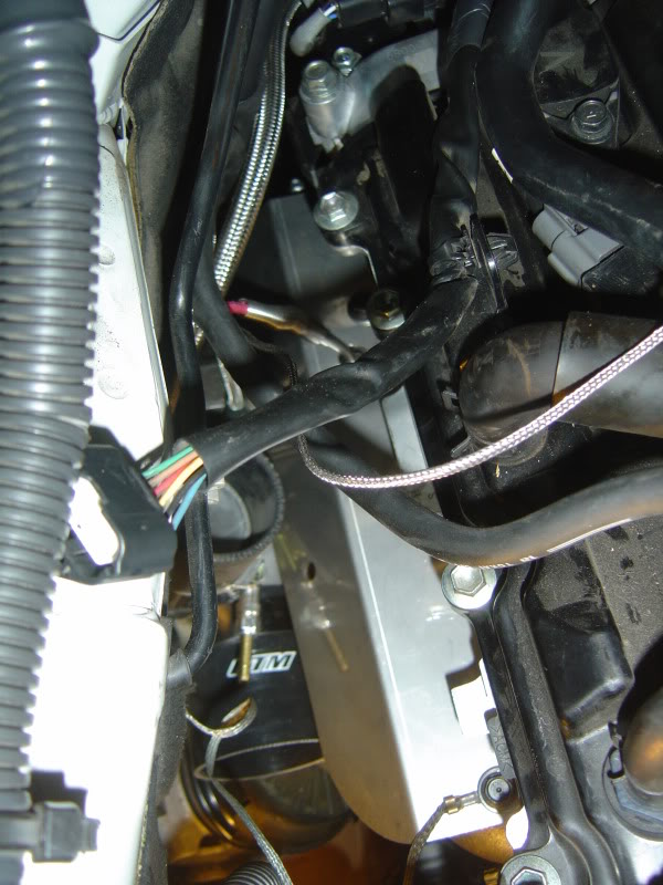
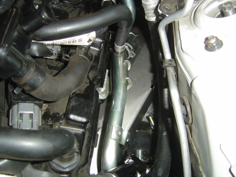
Running the IC piping:
It is very difficult to describe this process in words, so I’ll just try to provide a lot of pictures. One little advice, be careful when distinguishing the two pipes coming of the turbo charge housing. They look very similar and can get mixed up if youre not careful. I would suggest installing the passenger side first because only 1 of the pipes will fit the passenger side while both could fit the driver side.
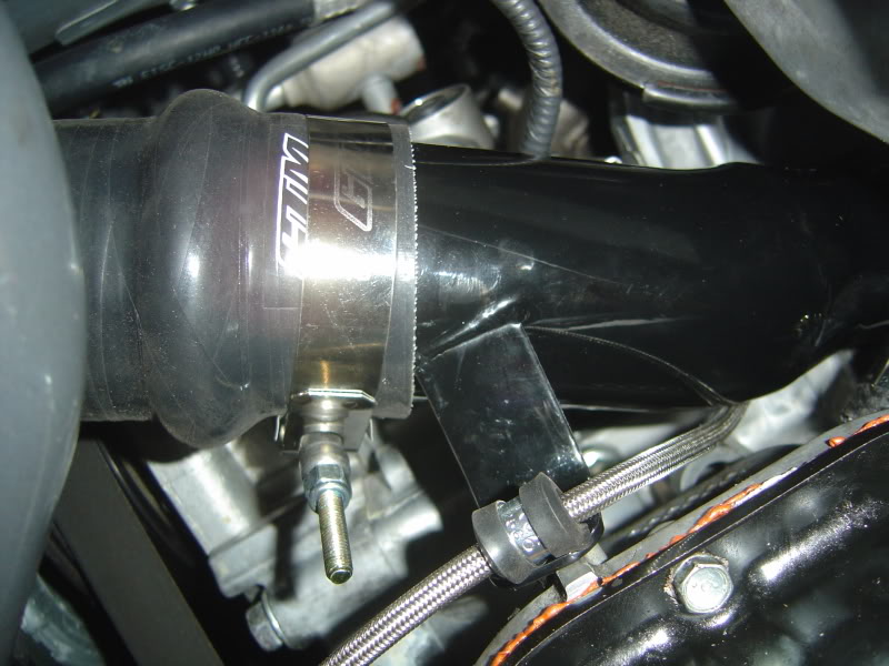
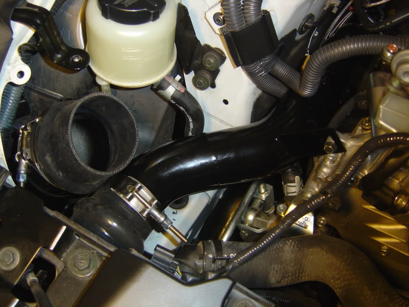
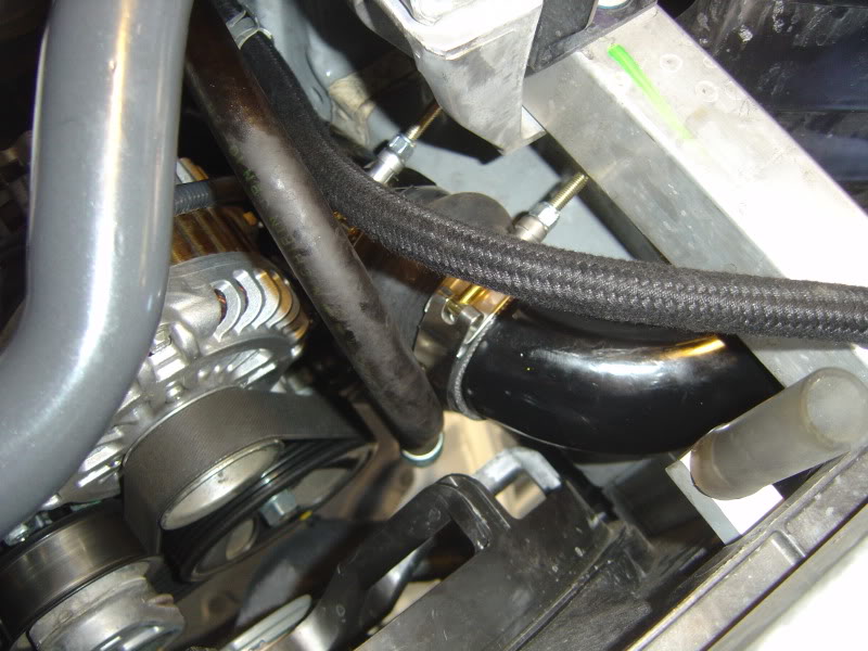
You will have to rerun the power steering tubes on the passenger side to clear all the IC tubing.
That’s it for now. I’d say my project is 90% complete at this point. Will still need to:
-secure the IC piping
-run the vacuum tubing
-install boost controller
Sorry for the late update everyone. I’ve been working hard on the install all weekend and did not have a chance to update the thread.
Mounting the turbo: The installation manual tells you to prepare the turbo by attaching the oil return drain and mounting the wastegate actuator. Don’t do it. If you leave the oil drain and actuator off, the mounting process is 100 times easier. It’s very easy to install those things after mounting the turbo anyways. Also, I would suggest that you install the engine mount spacers before attaching the turbos. It will give you more room to work with. You do not need to remove the clutch lines to install the driver side turbo but you need to take off the starter.
To mount the turbo, you need to add two studs to the rear side of the turbo manifold, place the gasket, and then attach the turbo. Orient everything as pictured. For the passenger side, you want the air intake side to face towards front of the car and the charge air pipe to face up towards the hood. For driver side, you need the intake side to face forward and the charge air pipe to face downward. You need to orient both turbos to have the drain tap face downward. Secure the two turbos with two nuts in the rear and two allen head bolts in the front.
Passenger side:
After mounting the turbo and orienting everything, you need to tighten all the brackets that secure the turbo housing. There are 6 bolts for the hot side and 6 for the cold side. Some of the bolts will be tricky to get to. Use crow’s foot attachments to help you secure the bolts. Leave the 2 bolts for the wastegate actuator on the cold side.
Then you need to add the coolant fitting:
Then you mount the wastegate actuator. This is a very important step and is a little tricky. You have to make sure the wastegate is just fully closed normally. You can adjust this by twisting the arm bracket on the actuator. Notice I had to bend the tip of the arm at a small angle to make sure the valve opens smoothly. Then tighten the bracket onto the turbo housing.
Now you can mount the oil drain. After that attach the exhaust manifold:
Do the same thing for the driver side.
Running water lines:
There are three different water lines. One line goes from driver side heater hose to turbo. Second line goes from turbo to turbo, and third line goes from passenger turbo to passenger heater hose.
Turbo heatshield:
These are very easy to install. Just move them around to get them to fit.
After attaching the heatshield on the driver side, you can reinstall the coolant piping:
Remounting the starter:
First you need to straight up the wire terminal that bolts to the starter. You have play around with the bracket and make it mount sideways as seen here:
You can also see the oil drain tubing.
Mounting the intercooler:
This is probably the easiest step. First line up the bracket correctly. Attach brackets to the intercooler but keep them loose. Then just attach to the car.
Remounting the steering column:
Push everything back in and use the provided spacers and longer bolt to mount the column. This makes sure that the steering column does not hit the turbo housing:
I did run into a problem while mounting the steering knuckle.
The factory steering rod has 2 alignment groves like this:
However, the GTM knuckle only had 1 grove so it wouldn’t go in the steering rod. I had to drill another alignment grove to make it fit. Assemble the knuckle like this:
The longer portion goes into the steering rod and the shorter section goes into the blue steering column.
Running the IC piping:
It is very difficult to describe this process in words, so I’ll just try to provide a lot of pictures. One little advice, be careful when distinguishing the two pipes coming of the turbo charge housing. They look very similar and can get mixed up if youre not careful. I would suggest installing the passenger side first because only 1 of the pipes will fit the passenger side while both could fit the driver side.
You will have to rerun the power steering tubes on the passenger side to clear all the IC tubing.
That’s it for now. I’d say my project is 90% complete at this point. Will still need to:
-secure the IC piping
-run the vacuum tubing
-install boost controller
Last edited by Modme; Sep 28, 2009 at 03:19 PM.
Update!!
09/29/09
The car was about 95% done. The vacuum lines were ran and all the brackets were tightened. But the sensors have not been setup yet. However, because Sam sent me the ECU flash, I was eager to fire her up to see if the install went okay.
So i went on to flash the ecu with Osiris. It's really straight forward. Plug in the cable, run osiris, load the tune and press flash. It takes about 2-3 minutes for the flash process. However, at the end of the flash, i got the error "Soft Reset error, contact Uprev"
I was getting ready to panic but decided to try to start the car anyways. Pressed the start button once, and then car cranked for 2 seconds and did not start. (Starting to really panic). Tried it again and the car seemed to start for a second and then dies. (Heart pounding now) I turned the car off and checked under the hood for any harness or tubes that I forgot to connect. But everything was fine. Went back into the car and gave it another try.....and......vroooommmmmm...She's alive!
Just as I was about to celebrate, coolant started pouring from the bottom of the car. Back to the drawing board...
09/30/09
Had to backtrack a few steps to figure out where the coolant is leaking from. It turned out to be from the water lines to the turbos. Apparently, you need to tighten the water lines very tightly. If not, coolant will pour out like a drain. Given the tight spaces, it's almost impossible to torque the water lines enough. I had to get really creative and create a special socket. I'll post pics tomorrow.
10/04/09
Car is up and running! I got a little impatient with the install and just wanted to get the thing done. So I did not take much pictures. All the coolant leaks have been fixed. Will post videos soon.
I went for a couple of test drives and all I can say is WOW! I havent even pushed the car yet but the difference is already astonishing. I'm still doing some preliminary road testing to make sure there is no leaks, rubbing, or overheating. This project is 98% done!
10/15/09
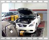
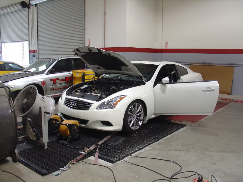
Brought it to Sam at GTM today for a dyno + tune. Apparently, Sam had sent me a low power tune, just to make sure everything is safe until I get the car on the dyno. First run pulled 380whp. Sam did a couple of things and the car is up to 430whp:
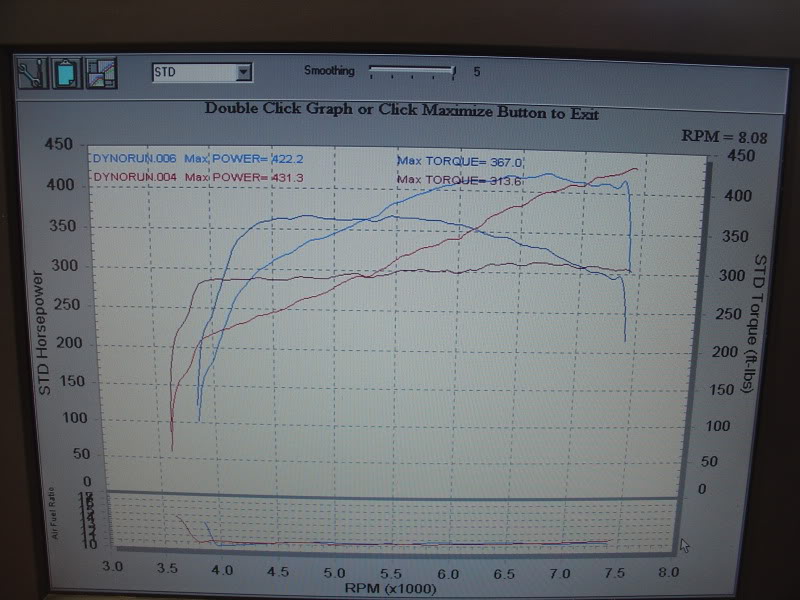
This is at about 6 psi. Keep in mind that I am running Berk HFCs and 2.5" FI exhaust.
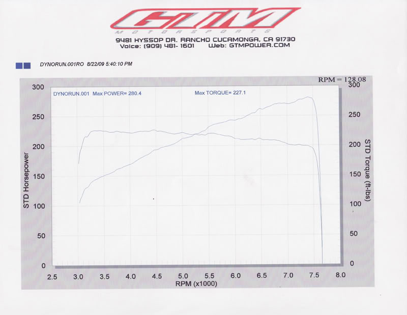
This is the before turbo dyno:
We wanted to turn up more boost but the car won't boost any higher. I'm pretty sure that I did not set the spring preload tight enough, so the internal wastegate is opening up. I'll get that fixed soon.
Here's a video on the dyno:
09/29/09
The car was about 95% done. The vacuum lines were ran and all the brackets were tightened. But the sensors have not been setup yet. However, because Sam sent me the ECU flash, I was eager to fire her up to see if the install went okay.
So i went on to flash the ecu with Osiris. It's really straight forward. Plug in the cable, run osiris, load the tune and press flash. It takes about 2-3 minutes for the flash process. However, at the end of the flash, i got the error "Soft Reset error, contact Uprev"
I was getting ready to panic but decided to try to start the car anyways. Pressed the start button once, and then car cranked for 2 seconds and did not start. (Starting to really panic). Tried it again and the car seemed to start for a second and then dies. (Heart pounding now) I turned the car off and checked under the hood for any harness or tubes that I forgot to connect. But everything was fine. Went back into the car and gave it another try.....and......vroooommmmmm...She's alive!
Just as I was about to celebrate, coolant started pouring from the bottom of the car.
Back to the drawing board...09/30/09
Had to backtrack a few steps to figure out where the coolant is leaking from. It turned out to be from the water lines to the turbos. Apparently, you need to tighten the water lines very tightly. If not, coolant will pour out like a drain. Given the tight spaces, it's almost impossible to torque the water lines enough. I had to get really creative and create a special socket. I'll post pics tomorrow.
10/04/09
Car is up and running! I got a little impatient with the install and just wanted to get the thing done. So I did not take much pictures. All the coolant leaks have been fixed. Will post videos soon.
I went for a couple of test drives and all I can say is WOW! I havent even pushed the car yet but the difference is already astonishing. I'm still doing some preliminary road testing to make sure there is no leaks, rubbing, or overheating. This project is 98% done!
10/15/09
Brought it to Sam at GTM today for a dyno + tune. Apparently, Sam had sent me a low power tune, just to make sure everything is safe until I get the car on the dyno. First run pulled 380whp. Sam did a couple of things and the car is up to 430whp:
This is at about 6 psi. Keep in mind that I am running Berk HFCs and 2.5" FI exhaust.
This is the before turbo dyno:
We wanted to turn up more boost but the car won't boost any higher. I'm pretty sure that I did not set the spring preload tight enough, so the internal wastegate is opening up. I'll get that fixed soon.
Here's a video on the dyno:
Last edited by Modme; Oct 16, 2009 at 12:34 AM.


Trending Topics


Administrator
Joined: Aug 2008
Posts: 12,173
Likes: 244
From: Doha, Qatar
It would be nice to tell us more about your background (as in how inclined are you when it comes to doing self-installs) edited in your first post maybe?
And definitely keep us posted please
Subscribed
And definitely keep us posted please
Subscribed